Soldering Page: Difference between revisions
| (4 intermediate revisions by the same user not shown) | |||
| Line 39: | Line 39: | ||
'''Stack overflow said check the diagram'''.<br> | '''Stack overflow said check the diagram'''.<br> | ||
[[File:Screenshot from 2022-10-29 13-43-11.png]]<br> | [[File:Screenshot from 2022-10-29 13-43-11.png]]<br> | ||
Finally I have one of these so it was useful. The display does not have polarity shown on it easily. On the back you can see pin 12.<br> | Finally I have one of these so it was useful. The display does not have polarity shown on it easily. On the back you can see pin 12 and bottom right pin 1<br> | ||
[[File:Tm | [[File:Tm display.png | 600px]]<br> | ||
In this case | |||
* Pin 1 = Square | |||
[[File:Tm solder.png]]<br> | |||
=Cleaning Flux= | |||
The host used isopropyl alcohol to clean excess flux from the PCB using an old toothbrush. | |||
Latest revision as of 04:11, 29 October 2022
Introduction
All things soldering or should I say sodering gar damn
Mine
Here is mine. [Hakko FX-888d]
Manual
Temperature
On the video it 400°C for lead free 450°C
Soldering a Resistor Wire
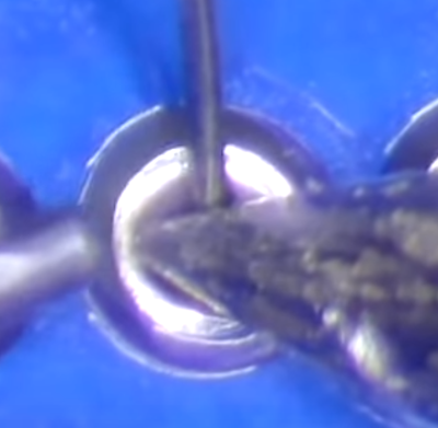
I used to want to melt the solder onto the joint but you need to heat the joint, in this case a resistor wire and the pad on the board together.
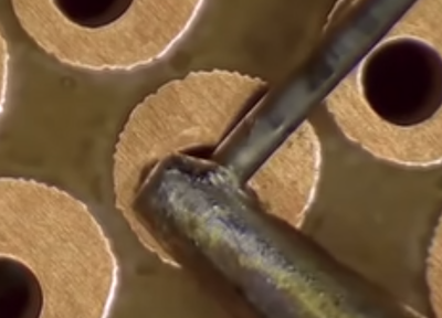
Then add the solder
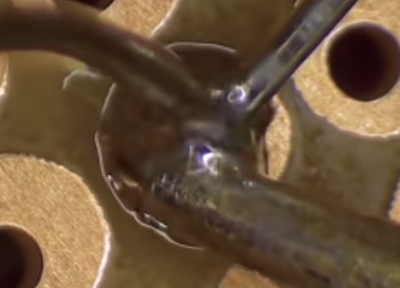
This is what finished looks like with resin around the outside
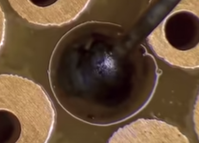
In this example, the person heated the pad and wire for 8 seconds before applying solder
Joining Wires
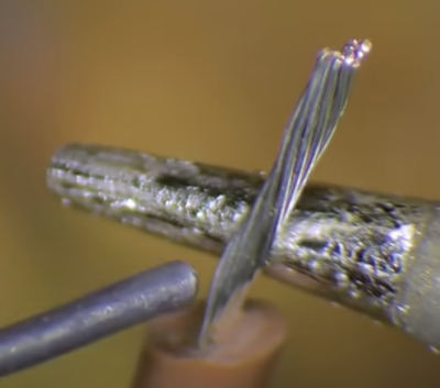
When joining wires, tin the wires first by heating the wire and then adding the solder.
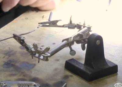
Add Heat shrink one end and Hold Wires in position
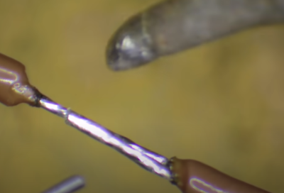
Next join the two wires together
Tools
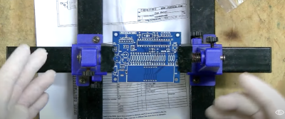
One recommendation was a PCB holder. You can buy these at [Jaycar]. These are small than they look and $25 NZD
App for Resistor Band. Resistor Toolkit
https://apps.apple.com/tr/app/resistor-toolkit-color-codes/id1058581945
Polarity
Some components require you put them the correct way around as each end has a different such as ICs. This means the +positive and -negative ends matter. Printed Circuit Boards will indicate which way either by specifying pin 1 or by specifying the polarity.
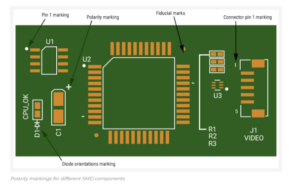
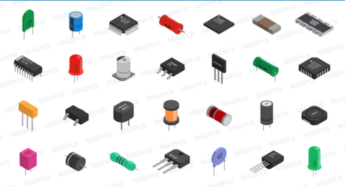
Most of these I would recognised as having polarity. e.g. IC or LED or Diode but the capacity was not known but I was unsurprised. The trick is to check.
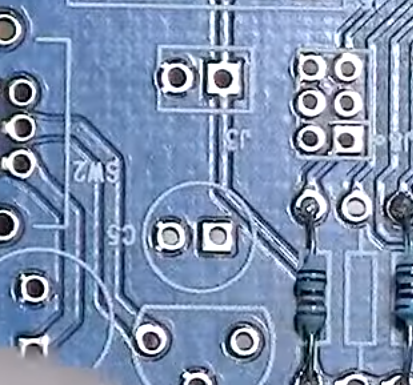
Round and Square holes on a PCB seem to mean something with regard to polarity but I could not find a site which supported a standard. Watching the youtube video Beginners Guide to Soldering Electronics Part 2 said
- + = Square and
- - = Round hole.
Stack overflow said check the diagram.
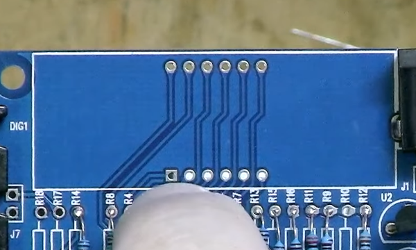
Finally I have one of these so it was useful. The display does not have polarity shown on it easily. On the back you can see pin 12 and bottom right pin 1

In this case
- Pin 1 = Square
Cleaning Flux
The host used isopropyl alcohol to clean excess flux from the PCB using an old toothbrush.
