Retrofit
Resource
During the course there were demo server APIs
https://github.com/alex-wolf-ps/RetrofitAPINode
https://github.com/alex-wolf-ps/RetrofitAPIDotnet
https://github.com/alex-wolf-ps/AndroidGlobomanticsApp
Getting Started
Permissions
We need to allow apps to use the internet so we need to add permissions to the manifest.
<uses-permission android:name="android.permission.INTERNET" />
Add Retrofit and Gson to Gradle
In the app gradle add
    implementation group: 'com.squareup.retrofit2', name: 'retrofit', version: '2.8.0'
    implementation group: 'com.squareup.retrofit2', name: 'converter-gson', version: '2.9.0'
Making a Request
Introduction
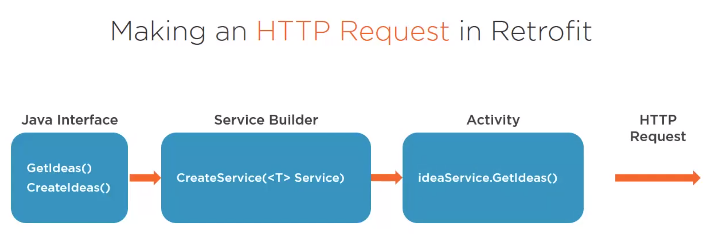
To do this we need to do three steps

Step 1 Define the interface
interface ContractService {
    @GET("contacts")
    Call<List<Idea>> getContacts()

    @POST("contract")
    Call<Idea> createContract(@Body Contact contact)

    @PUT("contracts")
    Call<Idea> updateContract(@Body Contact contact)

    @DELETE("contracts")
    Call<Idea> updateContract(@Path("id") int contactId)
}
Step 2 Configuring and Building the Service
We need to create a Build and Retrofit class
- Build Class, defines the configurations
- Retrofit Class, creates instances of the service
Step 3 Send And Receive
We can then use the service. For this we need to implement a
- Success Handler
- Error Handler
ideaService.getIdeas()
Worked Example 1
Here is a worked example
Step 1 Define the interface
Create create an interface which contains the end points for a collection of APIs
public interface MessageService{
    @GET("messages")
    fun getMessages(): Call<String>
}
Step 2 Configuring and Building the Service
    private const val URL = "http://10.0.2.2:9000/"

    private val builder = Retrofit.Builder().baseUrl(URL)
            .addConverterFactory(GsonConverterFactory.create())

    private val retrofit = builder.build()

    fun <S> buildService(serviceType: Class<S>?): S {
        return retrofit.create(serviceType)
    }
I use genymotion for speed when doing x86 projects so the local host for me was 192.168.56.1, and obtained using
ip a |grep vb
Step 3 Send And Receive
Within the activity we
- create an instance to the service.
- use the service
- handle the response and failure
        val taskService = buildService(MessageService::class.java)
        val call = taskService.getMessages()
        call.enqueue(object : Callback<String?> {
            override fun onResponse(request: Call<String?>, response: Response<String?>) {
                (findViewById<View>(R.id.message) as TextView).text = response.body()
            }

            override fun onFailure(request: Call<String?>, t: Throwable) {
                (findViewById<View>(R.id.message) as TextView).text = "Request Failed"
            }
        })
Worked Example 2
This is take from the bibbleCovid.
Step 1 Define the interface
interface BibbleCovidApi {

    @GET("covid/populations")
    fun getListPopulationCount(): Single<List<PopulationCountDTO>>
}
Step 2 Configuring and Building the Service
We going to be
- Creating a OkHttp client, this provides
- Creating a Retrofit instance with ReactiveX
Creating a OkHttp client
We create our own client because it provides better debugging tools and configuration, including
- timeouts
- Stetho Interceptor https://github.com/facebookarchive/stetho
- Chuck Interceptor https://github.com/jgilfelt/chuck
open class OkHttpClientFactory {

    open fun createOkHttpClient(context: Context): OkHttpClient =
        OkHttpClient.Builder()
            .apply {
                if (BuildConfig.DEBUG) {
                    enableDebugTools(context)
                }
                updateTimeout()
            }
            .build()

    private fun OkHttpClient.Builder.enableDebugTools(context: Context) {
        addInterceptor(StethoInterceptor())
        addInterceptor(ChuckInterceptor(context))
    }

    private fun OkHttpClient.Builder.updateTimeout(read: Long = 60, write: Long = 60) {
        readTimeout(read, TimeUnit.SECONDS)
        writeTimeout(write, TimeUnit.SECONDS)
    }
}
Creating a Retrofit
object RetrofitFactory {

    // Base URL: always ends with /
    private const val URL_MAIN_WEBSERVICE = "https://api.bibble.co.nz/"

    /**
     * Get [Retrofit] instance.
     * @return instances of [Retrofit]
     */
    @RequiresPermission(value = Manifest.permission.INTERNET)
    fun getRetrofit(
        context: Context,
        gson: Gson,
        okHttpClientFactory: OkHttpClientFactory
    ): Retrofit =
        Retrofit.Builder()
            .addCallAdapterFactory(RxJava3CallAdapterFactory.create())
            .addConverterFactory(GsonConverterFactory.create(gson))
            .baseUrl(URL_MAIN_WEBSERVICE)
            .client(okHttpClientFactory.createOkHttpClient(context))
            .build()
}
Step 3 Send And Receive
Adding Logging
Cannot believe the demo suggested logging can be a dry subject. Has to be the most important part of using new frameworks. Without the logging it is impossible to progress. Here goes - sorry about the rant.
For gradle we add
    implementation 'com.squareup.okhttp3:logging-interceptor:3.9.0'
    implementation 'com.squareup.okhttp3:logging-interceptor:4.9.0'
Now like Angular we add the use of the interceptors (UFO)
    private static HttpLoggingInterceptor logger =
            new HttpLoggingInterceptor().setLevel(HttpLoggingInterceptor.Level.BODY);

    // Create OkHttp Client
    private static OkHttpClient.Builder okHttp =
            new OkHttpClient.Builder().addInterceptor(logger);
We need to also add the okHttp to our builder retrofit builder too
    private val builder = Retrofit.Builder().baseUrl(URL)
            .addConverterFactory(GsonConverterFactory.create()).client(okHttp.build())
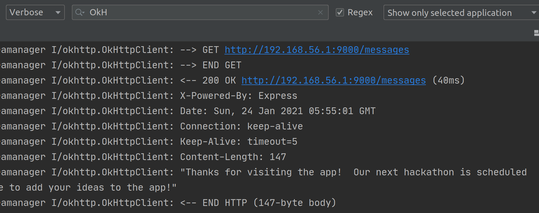
We can now see useful logs in the logcat

Parameters
Path Parameters
Path Parameters populate URL segment placeholders.
public interface IdeaService {
...
    @GET("ideas/{id}")
    fun getIdea(@Path("id") ideaId: Int): Call<Idea?>
}
Query Parameters
Query Parameters are automatically appended to the end of the URL
public interface IdeaService {
...
    @GET("ideas")
    fun getIdeas(@Query("status") status: String): Call<List<Idea?>?>
}
Combining
We can group these together
    @GET("ideas/{id}")
    fun getIdeas(
          @Path("id") ideaId: Int,
          @Query("status") status: String): Call<List<Idea?>?>
Or better still we can provide a query map which provides a named list of parameters
    @GET("ideas")
    fun getIdeas(@QueryMap parameters: Map<String, String>): Call<List<Idea?>?>
Example of using the QueryMap Filter
So below is an example filter using a map. Here is the interface
    @GET("ideas")
    fun getIdeas(@QueryMap owner: HashMap<String?, String?>?): Call<List<Idea?>?>?
And here is the code
...
    val filterMap = HashMap<String?, String?>()
    filterMap["owner"] = "Jim"
    filterMap["count"] = "1"
    val ideaService = buildService(IdeaService::class.java)
    val request = ideaService.getIdeas(filterMap)
    request?.enqueue(object : Callback<List<Idea?>?> {
       override fun onResponse(request: Call<List<Idea?>?>, response: Response<List<Idea?>?>) {
            recyclerView.adapter = SimpleItemRecyclerViewAdapter(response.body() as List<Idea>)
       }
       override fun onFailure(request: Call<List<Idea?>?>, t: Throwable) {
           (findViewById<View>(R.id.message) as TextView).text = "Request Failed"
       }
    })
Example CRUD Operations
GET
Service
    @GET("ideas/{id}")
    fun getIdea(@Path("id") ideaId: Int): Call<Idea?>
Implementation
            val ideaService = buildService(IdeaService::class.java)
            val request = ideaService.getIdea(arguments.getInt(ARG_ITEM_ID))
            request.enqueue(object : Callback<Idea?> {
                override fun onResponse(request: Call<Idea?>, response: Response<Idea?>) {
                    mItem = response.body()
                    ideaName.setText(mItem!!.name)
                    ideaDescription.setText(mItem!!.description)
                    ideaOwner.setText(mItem!!.owner)
                    ideaStatus.setText(mItem!!.status)
                    if (appBarLayout != null) {
                        appBarLayout.title = mItem!!.name
                    }
                }

                override fun onFailure(request: Call<Idea?>, t: Throwable) {
                    Toast.makeText(context, "Failed to retrieve item.", Toast.LENGTH_SHORT).show()
                }
            })
POST
Service
    @POST("ideas")
    fun createIdea(@Body newIdea: Idea?): Call<Idea?>?
Implementation
        val createIdea = findViewById<View>(R.id.idea_create) as Button
        val ideaName = findViewById<View>(R.id.idea_name) as EditText
        val ideaDescription = findViewById<View>(R.id.idea_description) as EditText
        val ideaOwner = findViewById<View>(R.id.idea_owner) as EditText
        val ideaStatus = findViewById<View>(R.id.idea_status) as EditText
        createIdea.setOnClickListener {
            val newIdea = Idea()
            newIdea.name = ideaName.text.toString()
            newIdea.description = ideaDescription.text.toString()
            newIdea.status = ideaStatus.text.toString()
            newIdea.owner = ideaOwner.text.toString()
            val ideaService = buildService(IdeaService::class.java)
            val request: Call<Idea> = ideaService.createIdea(newIdea)
            request.enqueue(object : Callback<Idea?> {
                override fun onResponse(request: Call<Idea?>, response: Response<Idea?>) {
                    val intent = Intent(mContext, IdeaListActivity::class.java)
                    startActivity(intent)
                }

                override fun onFailure(request: Call<Idea?>, t: Throwable) {
                    Toast.makeText(mContext, "Failed to create item.", Toast.LENGTH_SHORT).show()
                }
            })
PUT
This example shows how to use Url encoded.
Service
    @FormUrlEncoded
    @PUT("ideas/{id}")
    fun updateIdea(
        @Path("id")id: Int,
        @Field("name")name: String,
        @Field("description")desc: String,
        @Field("status")status: String,
        @Field("owner")owner: String): Call<Idea?>?
Implementation
            val ideaService = buildService(IdeaService::class.java)
            val request = ideaService.updateIdea(
                    arguments.getInt(ARG_ITEM_ID),
                    ideaName.text.toString(),
                    ideaDescription.text.toString(),
                    ideaStatus.text.toString(),
                    ideaOwner.text.toString()
            )

            request!!.enqueue(object : Callback<Idea?> {
                override fun onResponse(request: Call<Idea?>, response: Response<Idea?>) {
                    val intent = Intent(context, IdeaListActivity::class.java)
                    startActivity(intent)
                }

                override fun onFailure(request: Call<Idea?>, t: Throwable) {
                    Toast.makeText(context, "Failed to retrieve item.", Toast.LENGTH_SHORT).show()
                }
            })
DELETE
Service
    @DELETE("ideas/{id}")
    fun deleteIdea(@Path("id")id: Int): Call<Void>
Implementation
            deleteRequest.enqueue(object : Callback<Void?> {
                override fun onResponse(request: Call<Void?>, response: Response<Void?>) {
                    val intent = Intent(context, IdeaListActivity::class.java)
                    startActivity(intent)
                }

                override fun onFailure(request: Call<Void?>, t: Throwable) {
                    Toast.makeText(context, "Failed to delete item.", Toast.LENGTH_SHORT).show()
                }
            })        }
Other Stuff
Headers Basic
We can add static headers to the requests using the @Headers annotation @Headers({
       "Accept: application/json",
       "User-Agent: Your-App-Name",
       "Cache-Control: max-age=640000"
   })
Headers Map
val header = HashMap<String, String>()
    header["Accept"] = "application/json"
    header["Content-Type"] = "application/json"
    header["Authorization"] = "userToken"

// On the request
@POST("addresses")
    fun newAddress(@
          HeaderMap headers: Map<String, String>,
          @Body body: NewAddressBody): Single<Response<NewAddressResponse>>
Interceptors
Like angular we can create interceptors to add data to headers. Just like angular the ordering for these are important
                    .addInterceptor(new Interceptor() {
                        @Override
                        public Response intercept(Chain chain) throws IOException {
                            Request request = chain.request();

                            request = request.newBuilder()
                                    .addHeader("x-device-type", Build.DEVICE)
                                    .addHeader("Accept-Language", Locale.getDefault().getLanguage())
                                    .build();

                            return chain.proceed(request);
                        }
                    })
Timeouts
We can add timeouts and I am sure many other others.
    // Create OkHttp Client
    private val okHttp: OkHttpClient.Builder = OkHttpClient.Builder()
            .readTimeout(15, TimeUnit.SECONDS)
            .addInterceptor(Interceptor { chain ->
                var request = chain.request()
                request = request.newBuilder()
                        .addHeader("x-device-type", Build.DEVICE)
                        .addHeader("Accept-Language", Locale.getDefault().language)
                        .build()
                chain.proceed(request)
            })
            .addInterceptor(logger)
Cancelling Requests
To cancel a request we just call cancel on the request and the request will go to the onFailure branch.e.g
request.cancel()
Overriding Url
Not sure why this is in retrofit but here it is. We can override the Url for a service with the Url annotation
val call = taskService.getMessages("http://192.168.56.1:9000/messages")
...
interface MessageService {
    @GET
    fun getMessages(@Url altUrl: String?): Call<String?>?
}