Electronic Formulas Page: Difference between revisions
| (24 intermediate revisions by the same user not shown) | |||
| Line 42: | Line 42: | ||
= 14.4Ω (calculated from the meter reading and the input voltage) - 12.11Ω (Calculated from total resistance) = 2.29Ω | = 14.4Ω (calculated from the meter reading and the input voltage) - 12.11Ω (Calculated from total resistance) = 2.29Ω | ||
</syntaxhighlight> | </syntaxhighlight> | ||
=Resistance in Parallel= | |||
We measure resistance in parallel e.g. <br> | |||
[[File:Resister in parallel.png|400px]]<br> | |||
With the following formula<br> | |||
[[File:Resistors calculation parallel.png|400px]]<br> | |||
Using the above demo for Ohms and two resistors and no accounting for wire and multi-meters gives<br> | |||
[[File:Parallel demo.png]]<br> | |||
Recalculating adding these in gives<br> | |||
[[File:Demo circuit parallel with resistance.png|400px]] | |||
=Voltage Divider= | |||
Here we have a voltage divider. The purpose of this is what the name suggests to divide voltage.<br> | |||
[[File:Voltage divider diag.png|400px]]<br> | |||
And here is the formula used to calculate. You need to understand three of the parameters.<br> | |||
[[File:Voltage divider formula.png|400px]]<br> | |||
And here is what it looks like in reality where the input is on the right and the output on the left. Note the resistors in parallel.<br> | |||
[[File:Voltage Divider.png|600px]] | |||
=Power Rating= | |||
Here is a practical example of powering an LED of 2.2v on a 12v power supply with 0.02A of current<br> | |||
[[File:12v Led.png|600px]]<br> | |||
Doing the maths is | |||
<syntaxhighlight> | |||
V = 12v - 2.2v = 9.8v | |||
R = V/I = 9.8v/0.02 | |||
= 490Ω | |||
</syntaxhighlight> | |||
Putting the resistor is series will then mean it works. However when showing this example the power rating was a factor. This can be calculated by<br> | |||
[[File:Power rating.png|400px]]<br> | |||
Putting this into the formula gives | |||
<syntaxhighlight> | |||
P = V² ÷ R | |||
= 9.8² ÷ 490Ω | |||
= 96.04 ÷ 490 = 0.196 Watts. | |||
</syntaxhighlight> | |||
In the example the .5 Watt 550Ω worked well but the .25 Watt 390Ω resistor did not. This was because of the power rating. Using the formula | |||
<syntaxhighlight> | |||
96.04 ÷ 550 = 0.174 Watts | |||
96.04 ÷ 390 = 0.246 Watts | |||
</syntaxhighlight> | |||
We see the .25 Watt is not enough for the voltage. | |||
=Full Wave Rectifier= | |||
When we have AC current it flows from + to -. This produces and sine wave. We use a full wave rectifier to invert the wave and therefore half the amplitude by using diodes which control the flow of the current. Looking of the right of the picture you can see the result. A new sine wave with half the amplitude<br> | |||
[[File:Full Wave Rectifier.png|500px]]<br> | |||
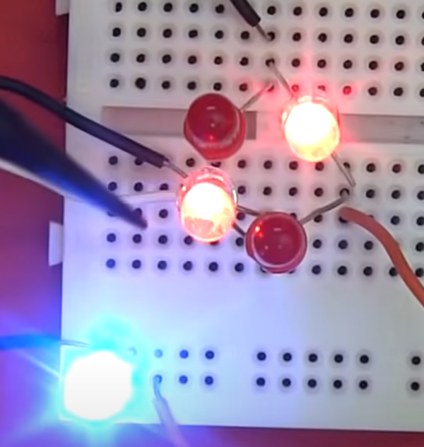
Change the type of diodes to LED we can demonstrate this circuit by slowing it done and watch the diodes alternatively powering the load LED diode<br> | |||
[[File:RectifierA.png|400px]] [[File:RectifierB.png|400px]]<br> | |||
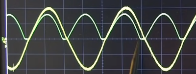
We can see the sine wave on the scope. Green is the AC Power, Yellow is the circuit<br> | |||
[[File:Scope rectifier.png|400]]<br> | |||
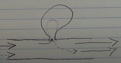
Ideally we want a current which is flat and constant. To fix this we can capture current as it arrive and distribute it back to flatten the curve. We use capacitors to do this.<br> | |||
[[File:Cap intro.png|400px]]<br> | |||
Demo showing wave before and after Cap<br> | |||
[[File:Rectifier without cap really.png|400px]]<br> | |||
[[File:Rectifier without cap.png|400px]] | |||
Latest revision as of 04:42, 4 December 2022
Ohms Law
Ohm’s law states that the voltage across a conductor is directly proportional to the current flowing through it, provided all physical conditions and temperatures remain constant.
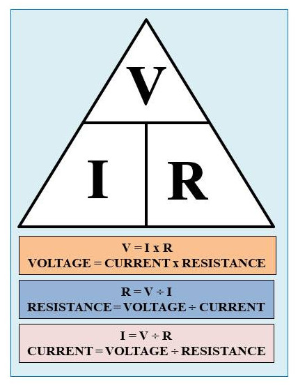
To demonstrate this a demo circuit was set up.
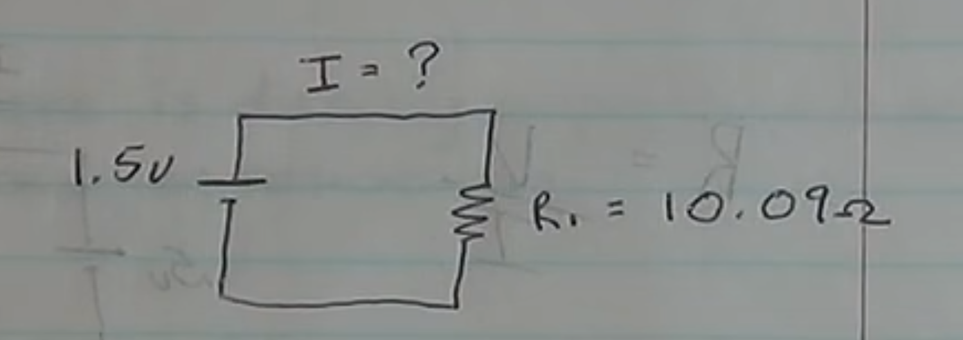
The circuit is put together and given the values the expected result is
1.5v ÷ 10.09Ω = 0.148A or 148mA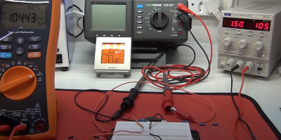
A you can see the answer was not as expected but instead 104.43mA. The reason for this is that the circuit has additional resistance due to the multi-meters.
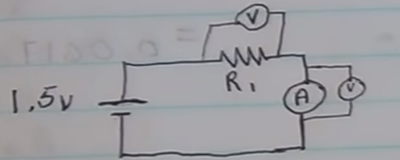
Luckily we are measuring these values
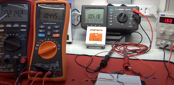
Looking a first measurement over the resistor
R₁ = V/I
= 1.05v ÷ 0.104A = 10.09Ω
Looking a second measurement over the multi-meter
Rₐ = V/I
= 0.21v ÷ 0.104A = 2.02Ω
Total Resistance calculated by adding together because we are in series
Rₜ = V/I
= 10.09Ω + 2.02Ω = 12.11Ω
Calculating the Total Amps
Amps = V/I
= 1.5 ÷ 12.11Ω = 0.123A or 123mA
Now lets calculate the Total Resistance using actual current meter reading (0.104A) and the (1.5) voltage.
R"ₜ" = V/I
     = 1.5v / 0.104A = 14.4Ω
Given we now know the actual resistance and the total resistance gives to the wiring resistance.
= 14.4Ω (calculated from the meter reading and the input voltage) - 12.11Ω (Calculated from total resistance) = 2.29ΩResistance in Parallel
We measure resistance in parallel e.g.
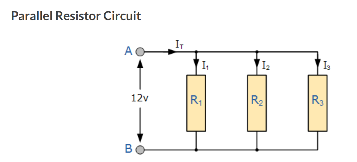
With the following formula

Using the above demo for Ohms and two resistors and no accounting for wire and multi-meters gives
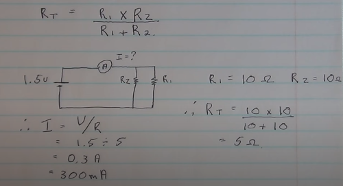
Recalculating adding these in gives

Voltage Divider
Here we have a voltage divider. The purpose of this is what the name suggests to divide voltage.

And here is the formula used to calculate. You need to understand three of the parameters.

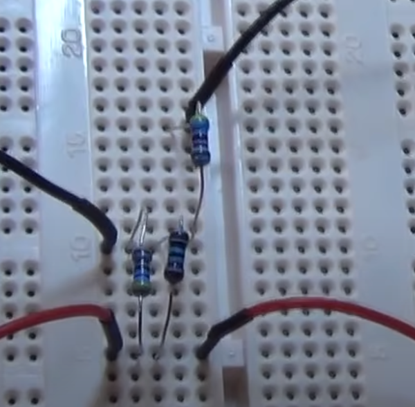
And here is what it looks like in reality where the input is on the right and the output on the left. Note the resistors in parallel.
Power Rating
Here is a practical example of powering an LED of 2.2v on a 12v power supply with 0.02A of current
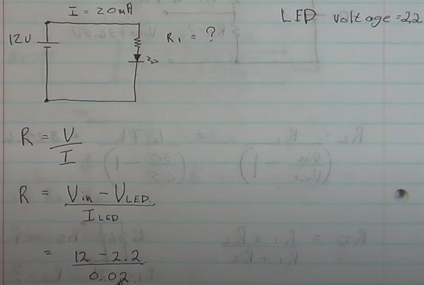
Doing the maths is
V = 12v - 2.2v = 9.8v
R = V/I = 9.8v/0.02
  = 490Ω
Putting the resistor is series will then mean it works. However when showing this example the power rating was a factor. This can be calculated by
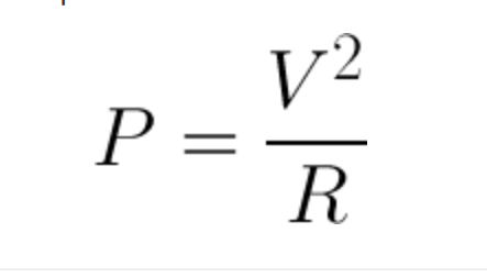
Putting this into the formula gives
P = V² ÷ R
  = 9.8² ÷ 490Ω
  = 96.04 ÷ 490 = 0.196 Watts.
In the example the .5 Watt 550Ω worked well but the .25 Watt 390Ω resistor did not. This was because of the power rating. Using the formula
  96.04 ÷ 550 = 0.174 Watts
  96.04 ÷ 390 = 0.246 Watts
We see the .25 Watt is not enough for the voltage.
Full Wave Rectifier
When we have AC current it flows from + to -. This produces and sine wave. We use a full wave rectifier to invert the wave and therefore half the amplitude by using diodes which control the flow of the current. Looking of the right of the picture you can see the result. A new sine wave with half the amplitude
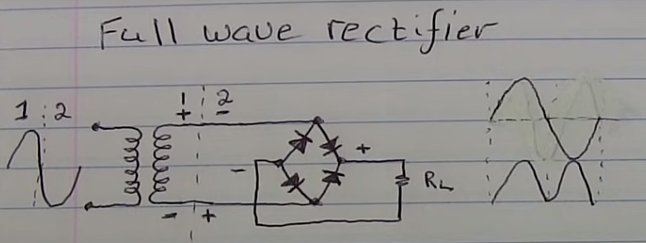
Change the type of diodes to LED we can demonstrate this circuit by slowing it done and watch the diodes alternatively powering the load LED diode
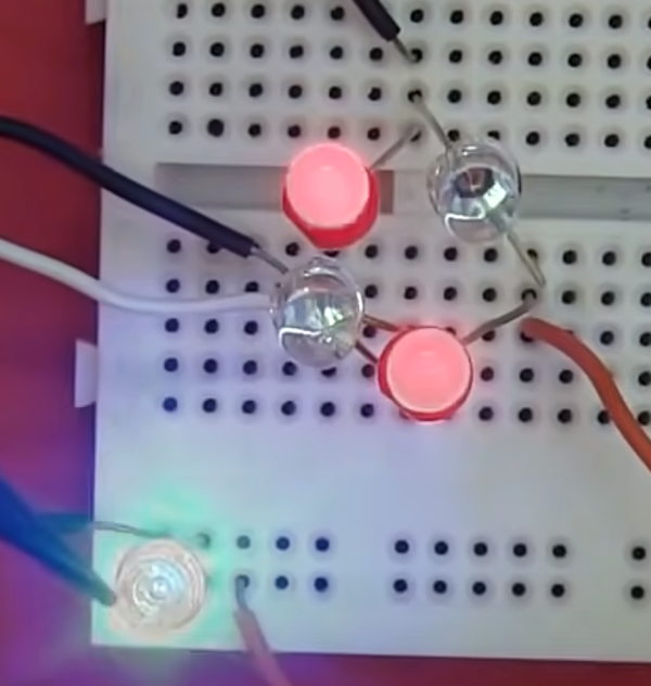
We can see the sine wave on the scope. Green is the AC Power, Yellow is the circuit
Ideally we want a current which is flat and constant. To fix this we can capture current as it arrive and distribute it back to flatten the curve. We use capacitors to do this.
Demo showing wave before and after Cap

