Digital Electronics Page: Difference between revisions
| Line 158: | Line 158: | ||
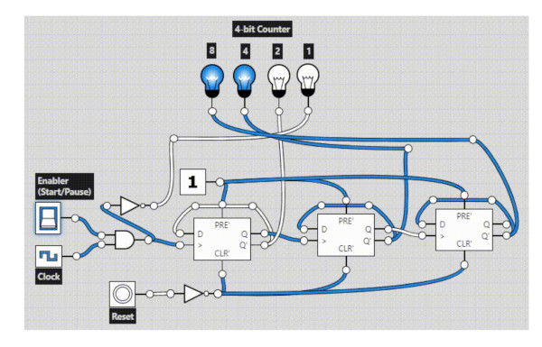
When using a falling edge D flip flop and feeding Q into clock we can create create a timer. The result of adding all of the Q values is 1 more each time<br> | When using a falling edge D flip flop and feeding Q into clock we can create create a timer. The result of adding all of the Q values is 1 more each time<br> | ||
[[File:D Latch Counter.jpg]]<br> | [[File:D Latch Counter.jpg]]<br> | ||
Here is the circuit<br> | |||
[[File:Flip Flop Time Circuit.jpg|500px]] | |||
Latest revision as of 01:03, 6 February 2023
Gray Codes
This is a technique where we convert number from binary to grays. We do this because Gray reduces the bits we need to change to get to the next number. e.g. changing from 2 to 3 decimal requires a 1 bit change.
| Decimal | BCD | Gray Code |
| 0 | 0000 | 0000 |
| 1 | 0001 | 0001 |
| 2 | 0010 | 0011 |
| 3 | 0011 | 0010 |
| 4 | 0100 | 0110 |
| 5 | 0101 | 0111 |
| 6 | 0110 | 0101 |
| 7 | 0111 | 0100 |
| 8 | 1000 | 1100 |
| 9 | 1001 | 1101 |
| 10 | 1010 | 1111 |
Excess-3 Codes
Conversion to Excess-3
To get an excess-3 code of a decimal number simply add 3 to each decimal digit. And then we write the 4-bit binary number for each digit of the decimal number. We can find the excess-3 code of the given binary number by using the following steps:
- We find the decimal number of the given binary number.
- Then we add 3 in each digit of the decimal number.
- Now, we find the binary code of each digit of the newly generated decimal number.
We can also add 0011 in each 4-bit BCD code of the decimal number for getting excess-3 code.
| Decimal | BCD | Excess-3 |
| 0 | 0000 | 0011 |
| 1 | 0001 | 0100 |
| 2 | 0010 | 0101 |
| 3 | 0011 | 0110 |
| 4 | 0100 | 0111 |
| 5 | 0101 | 1000 |
| 6 | 0110 | 1001 |
| 7 | 0111 | 1010 |
| 8 | 1000 | 1011 |
| 9 | 1001 | 1100 |
For example the excess-3 Code for 25.35 would be
25.35
33 33
-----
58 68
Which is
5 0100
8 1000
6 0110
8 1000
Therefore
01001000.01101000
Addition is Excess-3
Addition in Excess-3 is just binary addition with one more rule
If you need to carry a number you need to remove +3, if you don't carry a number you need to subtract 3. i.e. if the addition of a number result in an extra digit (carry) you need to add. An Example
Let's add 27 and 39
Step 1 Calculate Binary for numbers
 27 = 0010 0111
 39 = 0011 1001
Step 2 Calculate Excess-3 for these
 0010 0111
 0011 0011
 ---------
 0101 1010 <= Excess-3 for 27

 0011 1001
 0011 0011
 ---------
 0110 1100 <= Excess-3 for 39
Step 3 Add Excess-3 codes together
 0101 1010
 0110 1100
 ---------
      (carry 1)
 1000 0110
Step 4 Add or take away 3 from each side. In this case we carried on the right so we add and subtract on the left
 1000  0110
-0011 +0011
 ----------
 1001  1001
    9     9 <- This is the Excess-3 result NOT the answer we need to convert back to BCD to get the answer
Or we can convert the known answer 27 + 39 = 66 to Excess-3
   66      0110 0110
   33      0011 0011
 ----      ---- ----
   99      1001 1001
Signed Number
The signed numbers are represented in three ways.
- Sign-Magnitude form
In this form, a binary number has a bit for a sign symbol. 1=negative 0=Positive
- 1's Compliment.E.g 10101110 invert each bit 01010001.This is a positive number
- 2's Compliment. E.g 10101110 invert each bit 01010001 Then add 1 to the LSB of this result 01010001+1=01010010
Digital Logic Gates
This a IC which make decisions based on signals from there inputs. Basic digital logic gates perform logical operations of AND, OR and NOT on binary numbers.
There are commonly two types
- TTL Transitor-Transistor Logic such as 7400 series. They use NPN and PNP type PJTs
- CMOS Complementary Metal-Oxide-Silicon which is the 4000 series. They use MOSFET or JFET type Field Effect Transistors
You can also make these by using Diodes, Transistors and Resistors to produce an RTTL, Resistor, Transistor logic Gate.
Logic States
In digital logic design only two voltage levels or states are allowed and these states are generally referred to as Logic “1” and Logic “0”, or HIGH and LOW, or TRUE and FALSE.
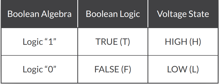
TTL and CMOS have the following Logic Levels

Note
- VCC refers to a common positive supply of bipolar ICs (no doubt related to a collector).
- VDD refers to the common positive supply of CMOS circuits (no doubt related to a drain)
NOT Gate
Truth Table
With each Gate comes a Truth Table. Here is the NOT gate
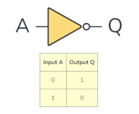
Circuit
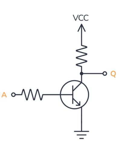
And here it is built as a circuit. If there is a current flow to ground. If
not current it flows to Q. Or more professionally put If A is HIGH, the transistor turns on. When the transistor is turned on, Q is pulled LOW through the transistor. If A is LOW, the transistor is off and Q is pulled HIGH through the resistor up to VCC.
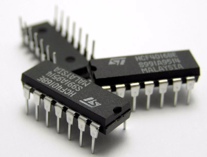
ICs
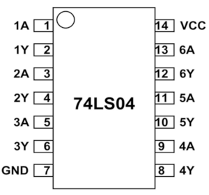
To make life a bit easier we can use integrated circuits for this.
Here is the pinout for a 74LS04
D-Latches
Types
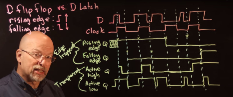
There are two of D Latches
Edge Triggered
For edge triggered D Latches there are two types, rising edge and falling edge. The rising edge stores the value in D at the time the clock rising. The falling edge stores the value in D at the time the clock falls.
Transparent
For transparent D latches there are two types, active high and active low. For active high the value of D is mimicked when the clock is high. The active low mimics the value of D when the clock is low.
Timings
Here are timings showing the different values of Q depending on the type of latch
Event Detection
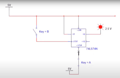
We can use a rising edge to detect an event. In the diagram below we can set a state using Key A in Q of the D-Latch. Once set we can tie Key B to the clock of the D-Latch. As long as the switch is closed Q remains constant. But if Key B is opened the value of Q changes and remains the same until another reset on Key A changes
D Flip-flop Clock Divider
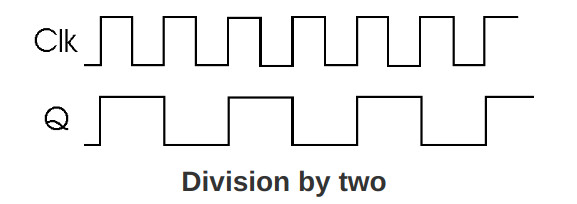
Using a rising edge flp-flop you can feed the clock into a flip flop.
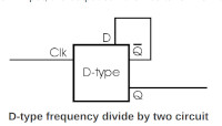
The output will be half frequency of the input
D Flip-flop Counter
When using a falling edge D flip flop and feeding Q into clock we can create create a timer. The result of adding all of the Q values is 1 more each time
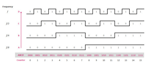
Here is the circuit
