Verilog Language: Difference between revisions
| Line 10: | Line 10: | ||
=Combinational Logic= | =Combinational Logic= | ||
This is where the outputs are a simple function of the inputs. (Sounds like pure functions | This is where the outputs are a simple function of the inputs. (Sounds like pure functions | ||
=2 to 1 Multiplexer= | ==2 to 1 Multiplexer using Combinational== | ||
This example shows the 3 approaches we can use to describe the hardware | This example shows the 3 approaches we can use to describe the hardware | ||
==Gate Level== | ===Gate Level=== | ||
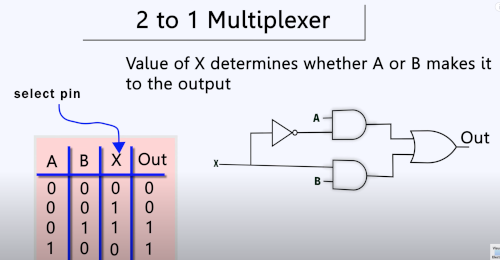
This was quite useful as I have some knowledge of gates and boolean logic so it starts to make a bit of sense in verilog. Here is the truth table for the 2 to 1 multiplexer<br> | This was quite useful as I have some knowledge of gates and boolean logic so it starts to make a bit of sense in verilog. Here is the truth table for the 2 to 1 multiplexer<br> | ||
[[File:Verilog example1a.png| 400px]]<br> | [[File:Verilog example1a.png| 400px]]<br> | ||
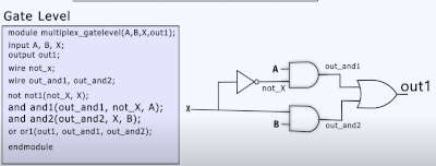
To model this at the gate level we could do this<br> | To model this at the gate level we could do this<br> | ||
[[File:Verilog example1b.png| 400px]]<br> | [[File:Verilog example1b.png| 400px]]<br> | ||
==Dataflow Level== | ===Dataflow Level=== | ||
And now the Dataflow level. This does look a lot like boolen logic and is very unreadable.<br> | And now the Dataflow level. This does look a lot like boolen logic and is very unreadable.<br> | ||
[[File:Verilog example1c.png| 400px]] | [[File:Verilog example1c.png| 400px]] | ||
===Behavioral Level=== | |||
==Behavioral Level== | |||
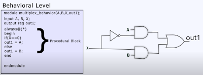
Finally the Behavioral Level which does seem more in my wheel house. The code uses a procedure block where the code only executes when there is a change in the signal<br> | Finally the Behavioral Level which does seem more in my wheel house. The code uses a procedure block where the code only executes when there is a change in the signal<br> | ||
[[File:Verilog example1d.png]]<br> | [[File:Verilog example1d.png]]<br> | ||
Revision as of 06:36, 17 December 2024
Introduction
This page is meant to help understand how to approach the language. There are three levels of abstraction.
Way to describe Hardware
- Gate Level
- Dataflow Level
- Behavioral Level
Types of Logic
- Combinational Logic
- Sequential Logic
Combinational Logic
This is where the outputs are a simple function of the inputs. (Sounds like pure functions
2 to 1 Multiplexer using Combinational
This example shows the 3 approaches we can use to describe the hardware
Gate Level
This was quite useful as I have some knowledge of gates and boolean logic so it starts to make a bit of sense in verilog. Here is the truth table for the 2 to 1 multiplexer

To model this at the gate level we could do this

Dataflow Level
And now the Dataflow level. This does look a lot like boolen logic and is very unreadable.

Behavioral Level
Finally the Behavioral Level which does seem more in my wheel house. The code uses a procedure block where the code only executes when there is a change in the signal

Sequential Logic
Sequential logic uses memory and state