Electronic Formulas Page: Difference between revisions
Jump to navigation
Jump to search
| Line 11: | Line 11: | ||
A you can see the answer was not as expected but instead 104.43mA. The reason for this is that the circuit has additional resistance due to the multi-meters.<br> | A you can see the answer was not as expected but instead 104.43mA. The reason for this is that the circuit has additional resistance due to the multi-meters.<br> | ||
[[File:Demo Circuit with multimeter.png]]<br> | [[File:Demo Circuit with multimeter.png]]<br> | ||
Luckily we are measuring these values<br> | |||
[[File:Demo circuit with multimeter reading.png]]<br> | |||
Looking a first measurement over the resistor | |||
<syntaxhighlight> | |||
R1 = V/I | |||
= 1.05v ÷ 0.104A = 10.09Ω | |||
</syntaxhighlight> | |||
Looking a second measurement over the multi-meter | |||
<syntaxhighlight> | |||
RA = V/I | |||
= 0.21v ÷ 0.104A = 2.02Ω | |||
</syntaxhighlight> | |||
Revision as of 00:37, 4 December 2022
Ohms Law
Ohm’s law states that the voltage across a conductor is directly proportional to the current flowing through it, provided all physical conditions and temperatures remain constant.
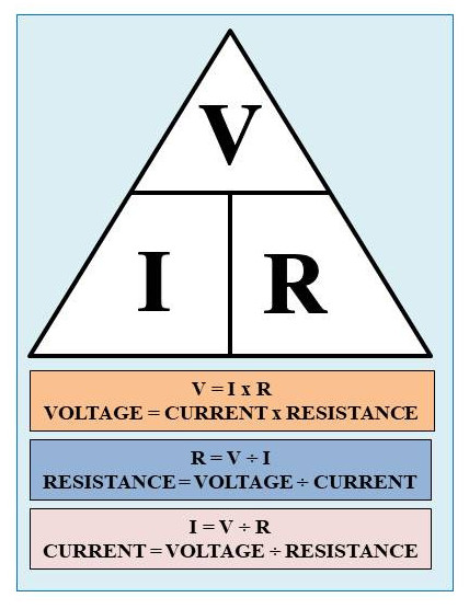
To demonstrate this a demo circuit was set up.
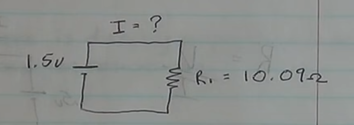
The circuit is put together and given the values the expected result is
1.5v ÷ 10.09Ω = 0.148A or 148mA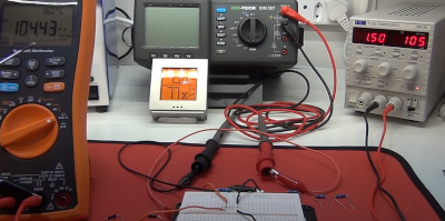
A you can see the answer was not as expected but instead 104.43mA. The reason for this is that the circuit has additional resistance due to the multi-meters.
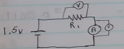
Luckily we are measuring these values
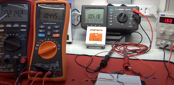
Looking a first measurement over the resistor
R1 = V/I
= 1.05v ÷ 0.104A = 10.09Ω
Looking a second measurement over the multi-meter
RA = V/I
= 0.21v ÷ 0.104A = 2.02Ω