Electronic Formulas Page: Difference between revisions
| Line 54: | Line 54: | ||
Here we have a voltage divider.<br> | Here we have a voltage divider.<br> | ||
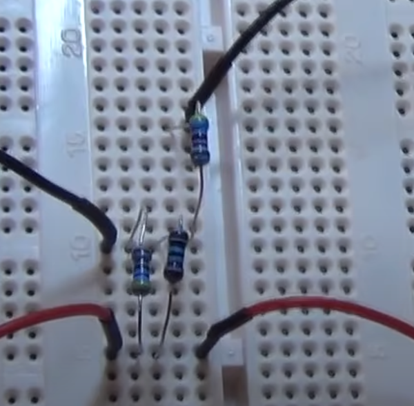
And here is what it looks like in reality where the input is on the right and the output on the left. Note the resistors in parallel. | And here is what it looks like in reality where the input is on the right and the output on the left. Note the resistors in parallel.<br> | ||
[[File:Voltage Divider.png|600px]] | [[File:Voltage Divider.png|600px]] | ||
Revision as of 02:03, 4 December 2022
Ohms Law
Ohm’s law states that the voltage across a conductor is directly proportional to the current flowing through it, provided all physical conditions and temperatures remain constant.
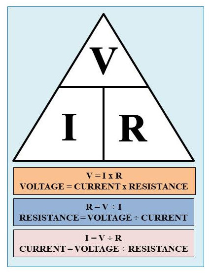
To demonstrate this a demo circuit was set up.
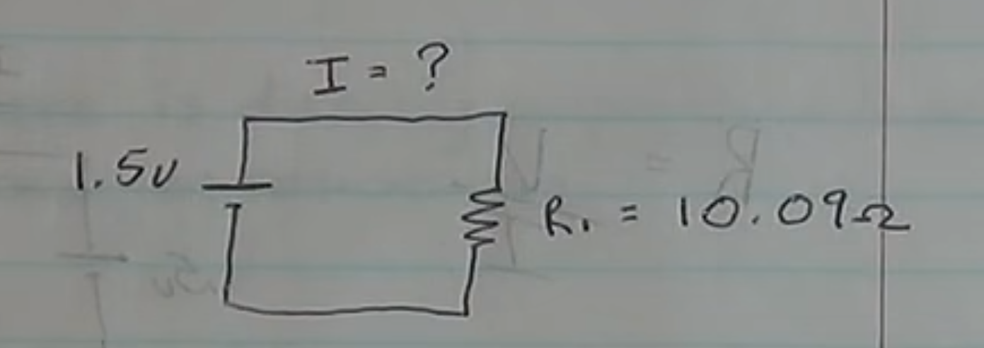
The circuit is put together and given the values the expected result is
1.5v ÷ 10.09Ω = 0.148A or 148mA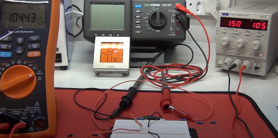
A you can see the answer was not as expected but instead 104.43mA. The reason for this is that the circuit has additional resistance due to the multi-meters.
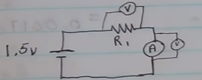
Luckily we are measuring these values
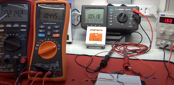
Looking a first measurement over the resistor
R₁ = V/I
= 1.05v ÷ 0.104A = 10.09Ω
Looking a second measurement over the multi-meter
Rₐ = V/I
= 0.21v ÷ 0.104A = 2.02Ω
Total Resistance calculated by adding together because we are in series
Rₜ = V/I
= 10.09Ω + 2.02Ω = 12.11Ω
Calculating the Total Amps
Amps = V/I
= 1.5 ÷ 12.11Ω = 0.123A or 123mA
Now lets calculate the Total Resistance using actual current meter reading (0.104A) and the (1.5) voltage.
R"ₜ" = V/I
     = 1.5v / 0.104A = 14.4Ω
Given we now know the actual resistance and the total resistance gives to the wiring resistance.
= 14.4Ω (calculated from the meter reading and the input voltage) - 12.11Ω (Calculated from total resistance) = 2.29ΩResistance in Parallel
We measure resistance in parallel e.g.
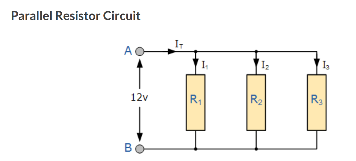
With the following formula

Using the above demo for Ohms and two resistors and no accounting for wire and multi-meters gives
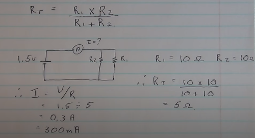
Recalculating adding these in gives

Voltage Divider
Here we have a voltage divider.
And here is what it looks like in reality where the input is on the right and the output on the left. Note the resistors in parallel.
