FPGA Page: Difference between revisions
| Line 22: | Line 22: | ||
*iCE40UltraUltraPlusSG48PinMigration.xlsx is the pinout really poorly named<br> | *iCE40UltraUltraPlusSG48PinMigration.xlsx is the pinout really poorly named<br> | ||
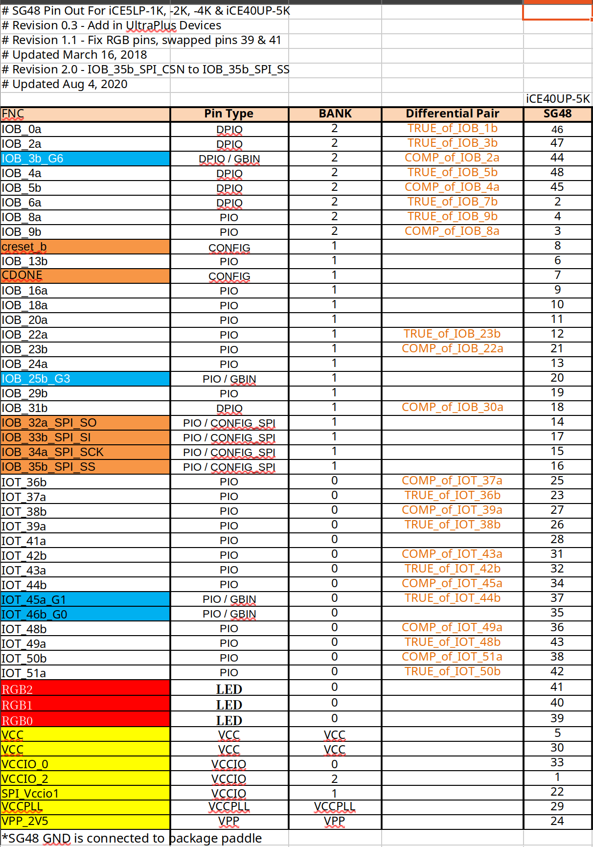
Here is the pinout<br> | Here is the pinout<br> | ||
[[File:Ice40up5k-b-evn pinout.png]] | [[File:Ice40up5k-b-evn pinout.png | 400px]] | ||
==Before project B== | ==Before project B== | ||
We need to install gtkwave with | We need to install gtkwave with | ||
Revision as of 20:54, 16 December 2024
Introduction
FPGA stands for Field-programmable gate array. I wish I had wrote this up last time but hey on the way now.
First Project
My first project was from Digikey videos [[1]] which I struggle with in several ways. So lets write them down so I do not forget
Python
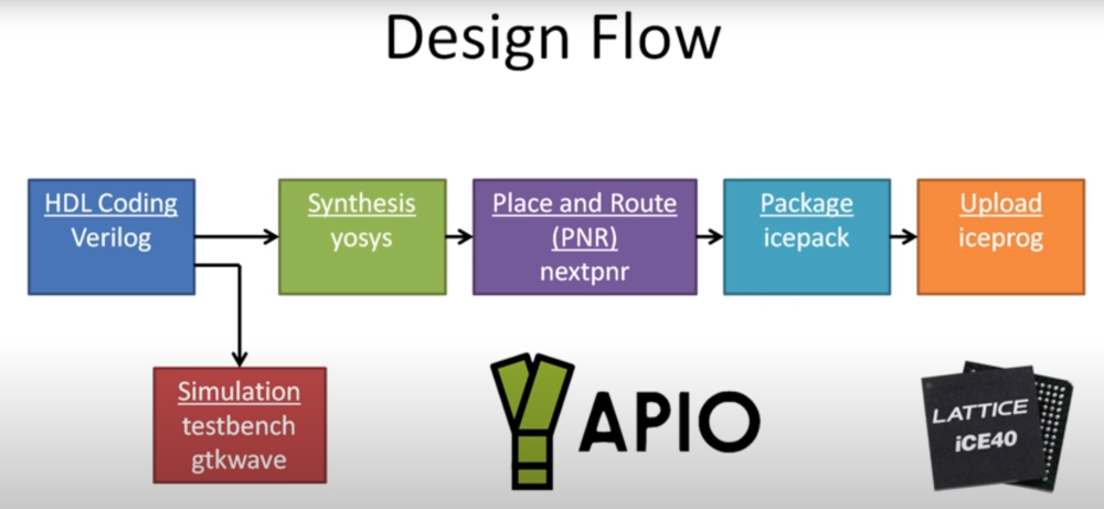
We us apio which is a python apt to make things easy. It loads the tools required to build a binary.
mkdir <project_name>
cd<project_name>
virtualenv venv
source venv/bin/activate
Install Apio
Install apio. He installed 0.6.3 but I mine worked on 0.9.5
pip apio
Before project A
Before creating the blink example we need to make sure we are configured for the correct board. For me this was the ice40up5k-b-evn which I believe it the marketing name. It was quite hard to track the chip down and therefore the pinout. I eventually found
- FPGAUG0200110.pdf which lists my board at the bottom once.
- iCE40UP5K-SG48 is the chip and listed under features
- iCE40UltraUltraPlusSG48PinMigration.xlsx is the pinout really poorly named
Before project B
We need to install gtkwave with
sudo apt install gtkwave
Fix up the tcl install as mine moaned about not have specific version. It first created a link for the /usr/local/lib with
sudo ln -s /usr/share/tcltk/tcl8.6 /usr/local/lib/
Then changed the init.tcl
#package require -exact Tcl 8.6.14
package require -exact Tcl 8.6.12
Create project
So we create a project using the examples provide with this command
apio examples -d icestick/leds
My default this creates a files called
- apio.ini
- led.pcf
The apio.ini contains the board and top module to use. For the board we need to fix this and we do so with
# To list the boards
apio boards --list
# And for us we use
apio init --board iCE40-UP5K
This then produces the following apio.ini file
[env]
board = iCE40-UP5K
top-module = main
We need to replace the main with the name of the first module which is leds
[env]
board = iCE40-UP5K
top-module = leds
Now we need to modify the project constraints file. This is a file which on the left has the name of the pin used in the project and on the right has you pin number. Because we used a icestick example the pins will be different. Here is the corrected file for the iCE40UP5K-SG48 based off the xls spreadsheet
# -----------------------------------------------------------------------------
#- Leds example for the iCEstick board
#- Constraint file (.pcf)
# -----------------------------------------------------------------------------
# --  Pinout: https://github.com/Obijuan/open-fpga-verilog-tutorial/blob/master/tutorial/doc/images/icestick_pinout.png
# --  Guide: https://github.com/Obijuan/open-fpga-verilog-tutorial/blob/master/tutorial/doc/icestickusermanual.pdf

# ------------ User Leds ------------------------------------------------------
set_io  D1 23
set_io  D2 25
set_io  D3 26
set_io  D4 27
set_io  D5 32
Now we are ready. No idea what some of these commands do and will not doubt file this in when I understand. Maybe just the sim I struggle with
# Parse the syntax
apio verify
# Simulate with gtkwave
apio sim
# Build
apio build
# Upload
apio upload

