STM32 Architecture
Introduction
This is the page for all things STM32. Currently working with a Nucleo F302R8
Setting Up
This was a trial and a half and here in case some others struggle and find this help.
STM32CubeIDE (Eclipse)
My goal was to use eclipse because this is what is used in the videos. So with ubuntu 23.04 install went to install this with eclipse. But the eclipse version requires python 2.7 which is no longer available.
VS Code
Luckily STM32 had brought out an extensions for my preferred solution VS Code. Installed the extension and went about installing the 3 other products it mentioned.
- STM32CubeMX
- STMCUFinder
- stm32cubeclt_1.12.1
Started it up but the import project button did nothing at all so I assumed it must need STM32CubeIDE. So went back to trying to install libpython2.7 and found https://askubuntu.com/questions/101591/how-do-i-install-the-latest-python-2-7-x-or-3-x-on-ubuntu. Unfortunately whatever I did must have move ld.so or something serious so had to re-install. But the good news was I could retry the STM32 extension. Having a new install I tried the STM32 Extension and it did indeed say could not find STM32CubeIDE. I documented this on the STM32 forum under https://community.st.com/s/question/0D53W00002IMDFZSA5/import-project-in-vs-code-ubuntu-2404
STM32CubeIDE Attempt 2
The was an additional install for STM32CubeIDE for vanilla linux. So I downloaded this and installed it. But on start up it failed with an error org.eclipse.swt.internal.C::strlen.
But the next morning googling I found https://github.com/adoptium/adoptium-support/issues/785 and the solution to getting it to work.
mkdir /tmp/SWT-GDBusServer
So may find solution was
- Ubuntu 23.04
- en.st-stm32cubeide_1.12.1_16088_20230420_1057_amd64.sh.zip
- en.ST-MCU-FinderLin_v5-0-0.zip
- en.stm32cubemx-lin-v6-8-1.zip
Debugging
Getting Started
Well now have all of the bits installed. Next it is time to start debugging
Update nucleo f302r8
This required an Update to the firmware. Google is your friend. Downloaded en.stsw-link007-v3-12-3.zip. This contained the udev rules which you can install using dpkg. Don't forget to reload rules with
sudo udevadm control --reload-rules
sudo udevadm trigger
Next under the stsw-link007/AllPlatforms
sudo java -jar STLinkUpgrade.jar
Hopefully this all goes well
Launch Settings
This was surprisingly easy once I had all the other things in place. Here is my file.
{
  "version": "0.2.0",
  "configurations": [

    {
      "name": "Debug via ST-Link",
      "cwd": "${workspaceRoot}",
      "type": "cortex-debug",
      "executable": "./build/debug/build/Test6.elf",
      "request": "launch",
      "servertype": "stlink",
      "device": "STM32F02R8",
      "interface": "swd",
      "runToEntryPoint": "main",
      "svdFile": "STM32F302.svd",
      "v1": false,
      "showDevDebugOutput": "both",
      "armToolchainPath": "/opt/st/stm32cubeclt_1.12.1/GNU-tools-for-STM32/bin"
  },
  ]
}
I used the following files for help
- Marus on Github https://github.com/Marus/cortex-debug/blob/master/debug_attributes.md
- MaJerle on Github https://github.com/MaJerle/stm32-cube-cmake-vscode/blob/main/README.md
Blinky
Did take me a while to read the documentation. Especially around finding the LEDs on the board. Starting a new app provided the proper view. Maybe it is something I need to learn. Also lost a bit of time putting the code in the main rather than in the while loop further down. So here is the setting of GPIO pins STM32 style.
  /* Infinite loop */
  /* USER CODE BEGIN WHILE */
  while (1)
  {
    /* USER CODE END WHILE */

      // HAL_GPIO_TogglePin(GPIOB, GPIO_PIN_13);
      // HAL_Delay(500);
      if(HAL_GPIO_ReadPin(GPIOC,GPIO_PIN_13) == GPIO_PIN_RESET) {
        HAL_GPIO_WritePin(GPIOB, GPIO_PIN_13, GPIO_PIN_SET);
        HAL_Delay(500);
        HAL_GPIO_WritePin(GPIOB, GPIO_PIN_13, GPIO_PIN_RESET);
      }

    /* USER CODE BEGIN 3 */
  }
  /* USER CODE END 3 */
Memory
Almost forgot to do this. So we now have this working in VS Code. Some brief reminders of some basics with regard to memory. So here is some simple code to copy some data from flash to the SRAM. On the board I have SRAM starts at 0x20000000.
char const myData[]  = "I love Programming";
#define BASE_ADDRESS_OF_SRAM 0x20000000

void foo2() {
  for(int i = 0; i < sizeof(myData); i++) {
    *((uint8_t*) BASE_ADDRESS_OF_SRAM +i ) = myData[i];
  }
}
With eclipse you can add a memory window and set the format to ASCII and then go to the location to see the copy.
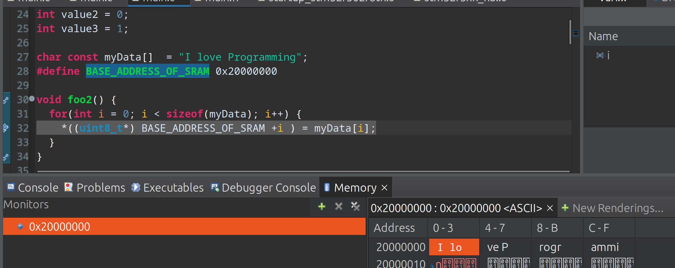
For VS Code I have struggled to get this going with hex 0x20000000 but for decimal 536870912 this works fine.

By adding &myData you can view the address in the memory view too. We can see here that myData is stored at 0x8002864. I have used the fred variable to demonstrate this. You can see the actual address is the first address in the memory view in yellow 0x8002864 however the display in white starts at 0x8002860.

System Architecture
Introduction
My knowledge is very small, no not just in general, but on this subject in computers. This is probably where I regret not having a degree. But here goes I am going to try and understand enough of the diagram from the STM32F0xx Cortex-M0 to be dangerous.
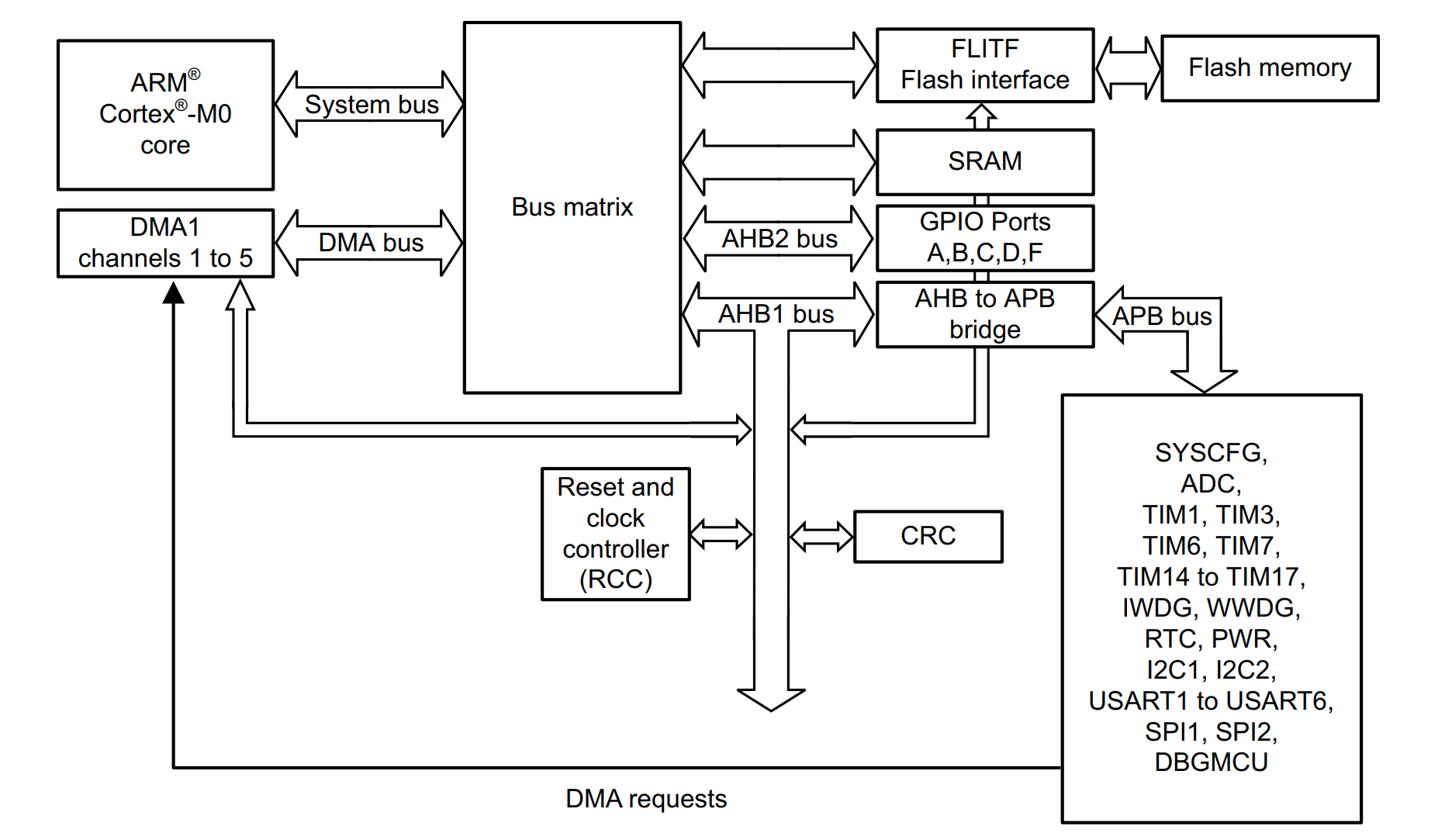
I am again looking at Intermation and their course which is Computer Organization and design.
Memory Hierarchy
There is a Hierarchy
- Registers
- Cache (L1 Local, L2 Shared)
- Main Memory (RAM)
- Long Term Storage (Hard Disks, Tapes etc)
Memory Device Interface
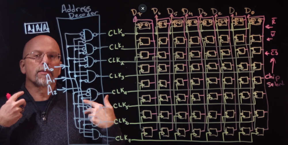
Here was shown how the circuit might work with D Flip-Flops and a clock line. Added was an address decoders to allow the device to select the right clock line. Three other signals are required, a write, a read and a chip select.
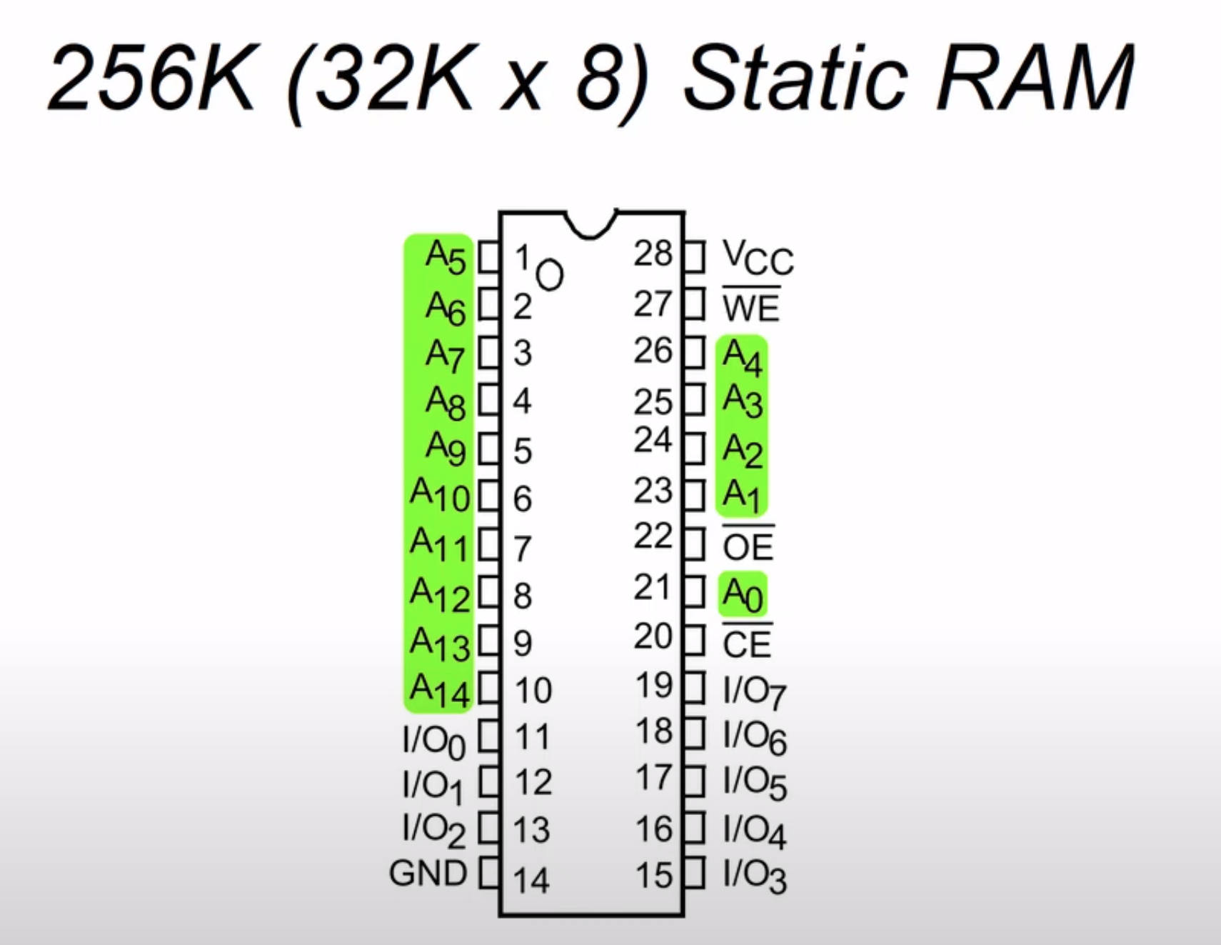
Ironically he went on to show this device which I reckon is the one I am using for the 6502.
Types Of Memory
- DRAM Dynamic RAM uses capacitors, slower, cheaper, requires refreshing
- SRAM Static RAM uses transistors, faster
Chip Select
When we look at an MCU there is a memory map which shows where the peripherals are on the device. Each device has a range of memory used to operate it.
There are address lines within the mcu which are connected to the device. In the example below there are 20 address lines and the Graphic Card is located between 0xE0000 and 0xFFFFF. Putting this number into binary shows that address lines A19-A17 is the CS (Chip Select) and address line A16-A00 is the graphic card. Setting A19-A17 to binary 111 effectively means you are using the address lines for the graphics card.
 In order to operate the correct memory device from the processor you use the correct chip select.
To maybe see a real world example here is windows showing us the memory map range for a device.
