Electronic Safety Page: Difference between revisions
Jump to navigation
Jump to search
| Line 37: | Line 37: | ||
*connect - of light bulb to - (ground) of power source | *connect - of light bulb to - (ground) of power source | ||
*turn power on | *turn power on | ||
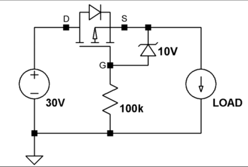
==Mosfet Protection Circuit== | |||
This circuit protects the user from accidentally connecting the power in reverse and is an improvement on just using a diode. In the example a MOSFET P Channel was used.<br> | |||
[[File:MOSFet Protection Curcuit.png]]<br> | |||
Revision as of 06:52, 6 January 2023
Introduction
This page is for all things Safety
Mulitimeter
- Set to DC because we not doing AC while I need to read this
- Positive (Red lead) to Positive
- Currently own QM1323
- Probes CAT III 1000v, 10A
- Don't let the probes touch
- Keep tips covers to reduce change of touching
- A negative reading means you have the probes in the wrong way
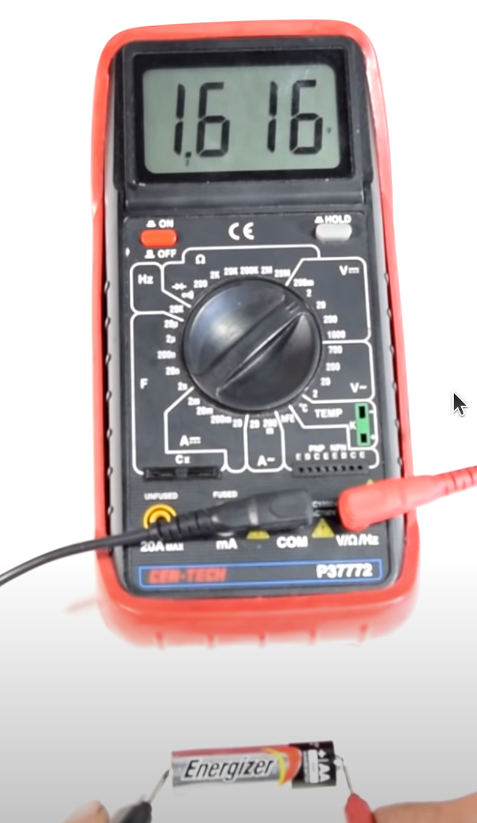
Measure Battery
- Identify +/- of battery
- Make sure battery is fixed in place
- Set Multimeter to V + DC current
- Plug black lead into COM, Red into non-10A or 20A
- negative black lead to -battery, positive red lead to +battery
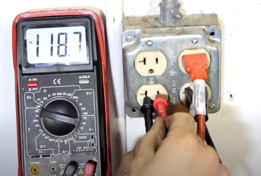
Measure Mains
Don't do this unless you know what you are doing. And do not let the lead touch when putting them into the slots
- Set Multimeter to V + AC current
- Plug black lead into COM, Red into non-10A or 20A
- negative black lead to earth, positive red lead to power
Measure Continuity
Testing for this means test for connectivity. I.E. is this a curcuit. We are not measuring volts only connectivity.This is done with the power off
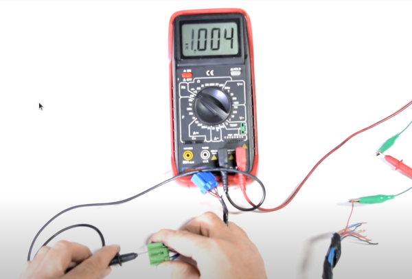
- Set Multimeter to V + AC current
- Set Mode to show speaker or no sound will occur
Measure Amps
Testing a light bulbs amps we need to insert the multimeter into the circuit.
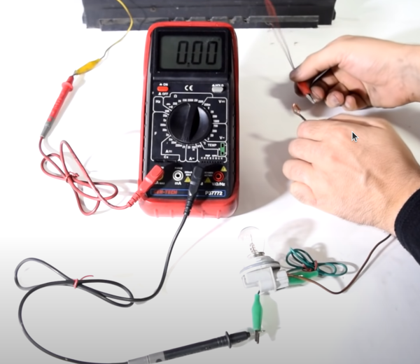
- turn power off
- put meter as the first item from the positive side of the power source
- set meter to 10A
- plug red probe on the meter into 10A
- connect black probe to + of the light bulb
- connect - of light bulb to - (ground) of power source
- turn power on
Mosfet Protection Circuit
This circuit protects the user from accidentally connecting the power in reverse and is an improvement on just using a diode. In the example a MOSFET P Channel was used.
