Electronic Safety Page
Introduction
This page is for all things Safety
Mulitimeter
- Set to DC because we not doing AC while I need to read this
- Positive (Red lead) to Positive
- Currently own QM1323
- Probes CAT III 1000v, 10A
- Don't let the probes touch
- Keep tips covers to reduce change of touching
- A negative reading means you have the probes in the wrong way
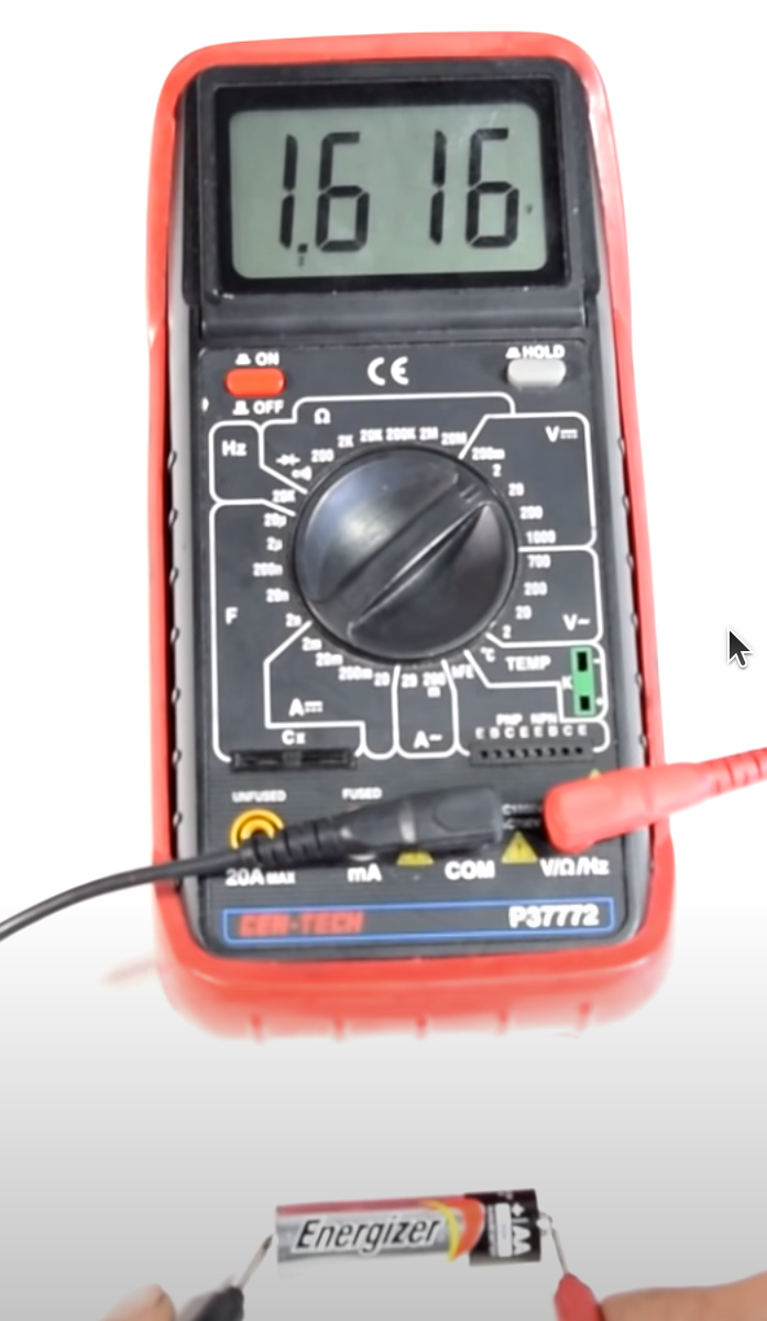
Measure Battery
- Identify +/- of battery
- Make sure battery is fixed in place
- Set Multimeter to V + DC current
- Plug black lead into COM, Red into non-10A or 20A
- negative black lead to -battery, positive red lead to +battery
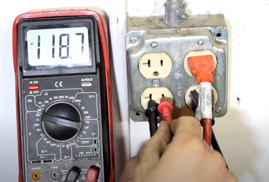
Measure Mains
Don't do this unless you know what you are doing. And do not let the lead touch when putting them into the slots
- Set Multimeter to V + AC current
- Plug black lead into COM, Red into non-10A or 20A
- negative black lead to earth, positive red lead to power
Measure Continuity
Testing for this means test for connectivity. I.E. is this a curcuit. We are not measuring volts only connectivity.This is done with the power off
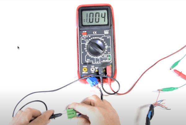
- Set Multimeter to V + AC current
- Set Mode to show speaker or no sound will occur
Measure Amps
Testing a light bulbs amps we need to insert the multimeter into the circuit.
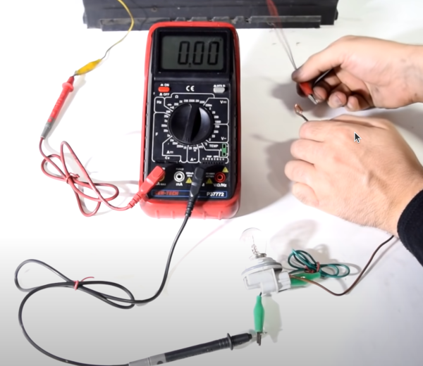
- turn power off
- put meter as the first item from the positive side of the power source
- set meter to 10A
- plug red probe on the meter into 10A
- connect black probe to + of the light bulb
- connect - of light bulb to - (ground) of power source
- turn power on
Oscilloscope Grounding
When you use Oscilloscope probes it is very important to ensure the circuit being probed is not grounded to the mains. I.E. the power on the circuit does not use mains power with an earth pin. A good example of this would be when you use a PC usb. Doing this means the PC, which is earthed to the mains will complete the circuit when you probe
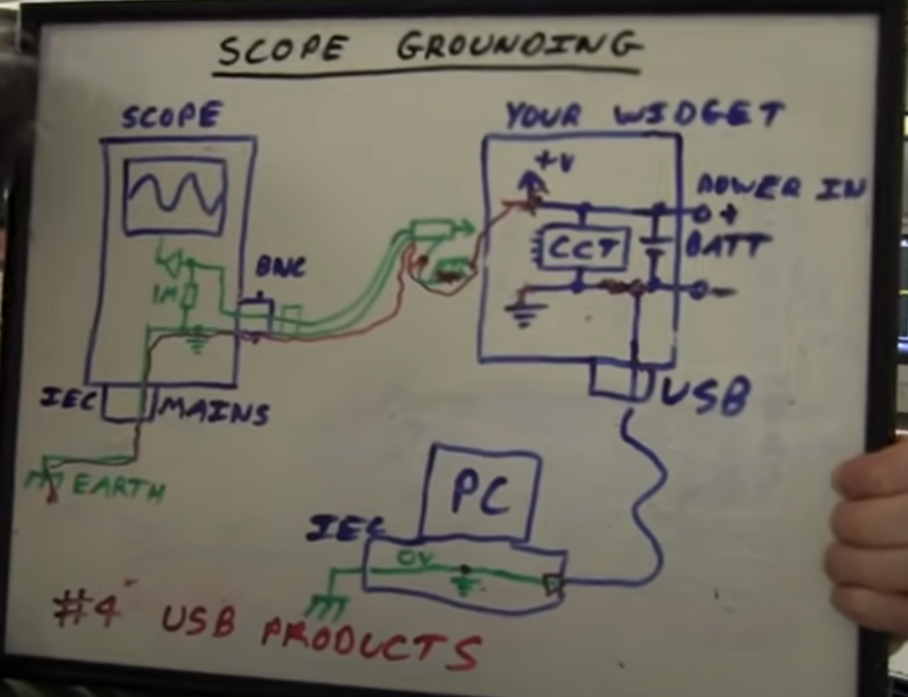
You can usually tell if the appliance is mains earth because the will have three pins rather than two.
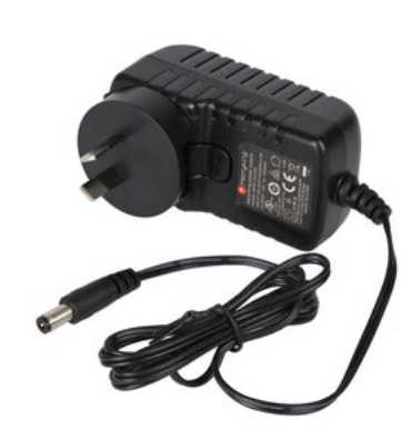
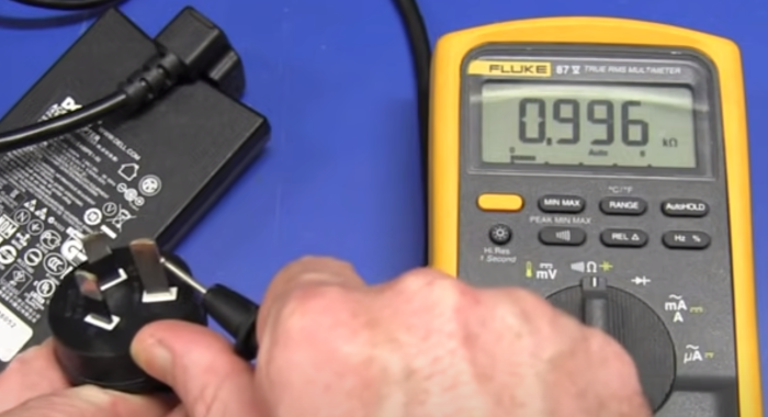
Here we see a toshiba power supply with an earth pin with 1k of resistance on the live pin. This means that when plugged in it will still have little protection for any current when probing. Don't do it
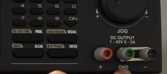
The bench power supply will have usually three pins +/- and ground, read, black and green. This means that the power supply is not mains earthed (provided you do not connect the earth). You can safely probe the circuit without shorting it out
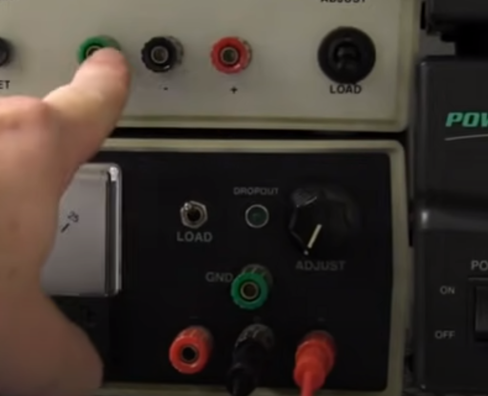
DON'T TO THIS. In some cases, the earth may be connected to the negative. Then you will need to be extremely careful when using the probes.
Mosfet Protection Circuit
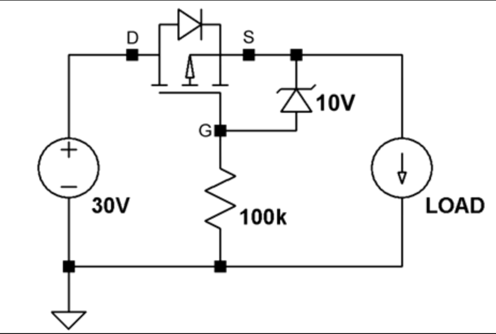
This circuit protects the user from accidentally connecting the power in reverse and is an improvement on just using a diode. In the example a MOSFET P Channel was used.
