Iain's Electronics Page: Difference between revisions
No edit summary |
|||
| Line 44: | Line 44: | ||
Basically they operate horizontally in the middle and vertically on the outside. Typically the outside rails are for the power supply.<br> | Basically they operate horizontally in the middle and vertically on the outside. Typically the outside rails are for the power supply.<br> | ||
[[File:Breadboard.png|300px]] | [[File:Breadboard.png|300px]] | ||
==Example Circuit=== | |||
We can see the ground is flowing vertically and the components are connected horizontally. | |||
[[File:Breadboard2.png|300px]] | |||
Revision as of 05:32, 23 October 2021
Using a Multimeter
Measuring Voltage
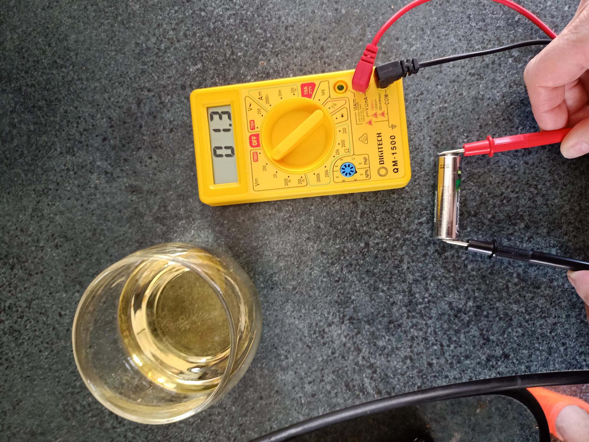
To measure voltage on a battery.This is an example of a 1.4 AA battery.
- black goes to the negative and red to the positive or knobbley end.
- make sure black lead is in COM on the multimeter
- make sure red lead is in V on the multimeter
- connecting in correctly will result in a negative number
- the numbers in the V section are the range in mA.
- using the 200mA will result in 1364 or 1.364 Volts
Measuring Voltage of a Circuit
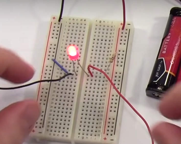
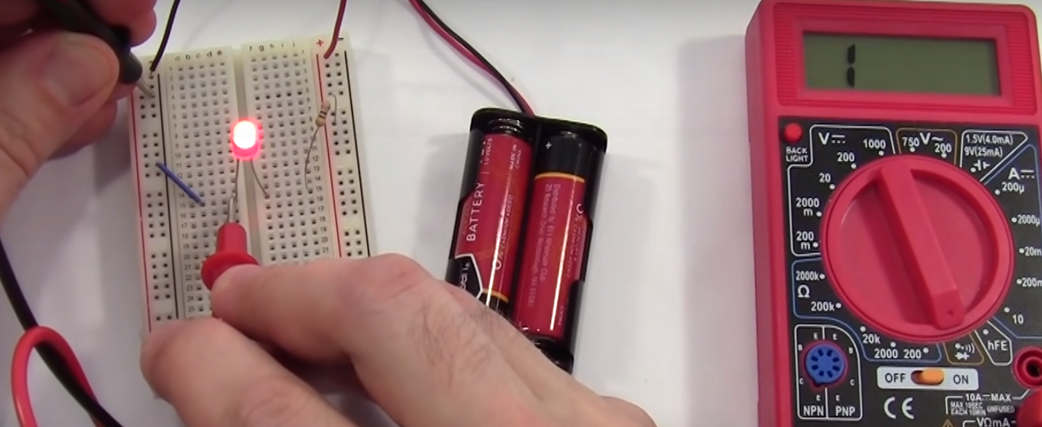
Below we have a circuit with a battery, resister and LED.
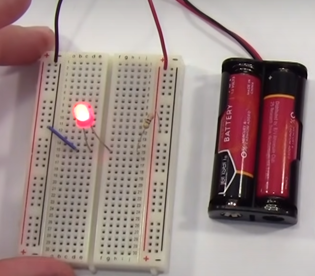
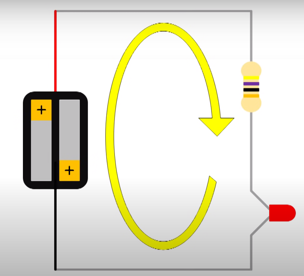
Here would be the circuit diagram.
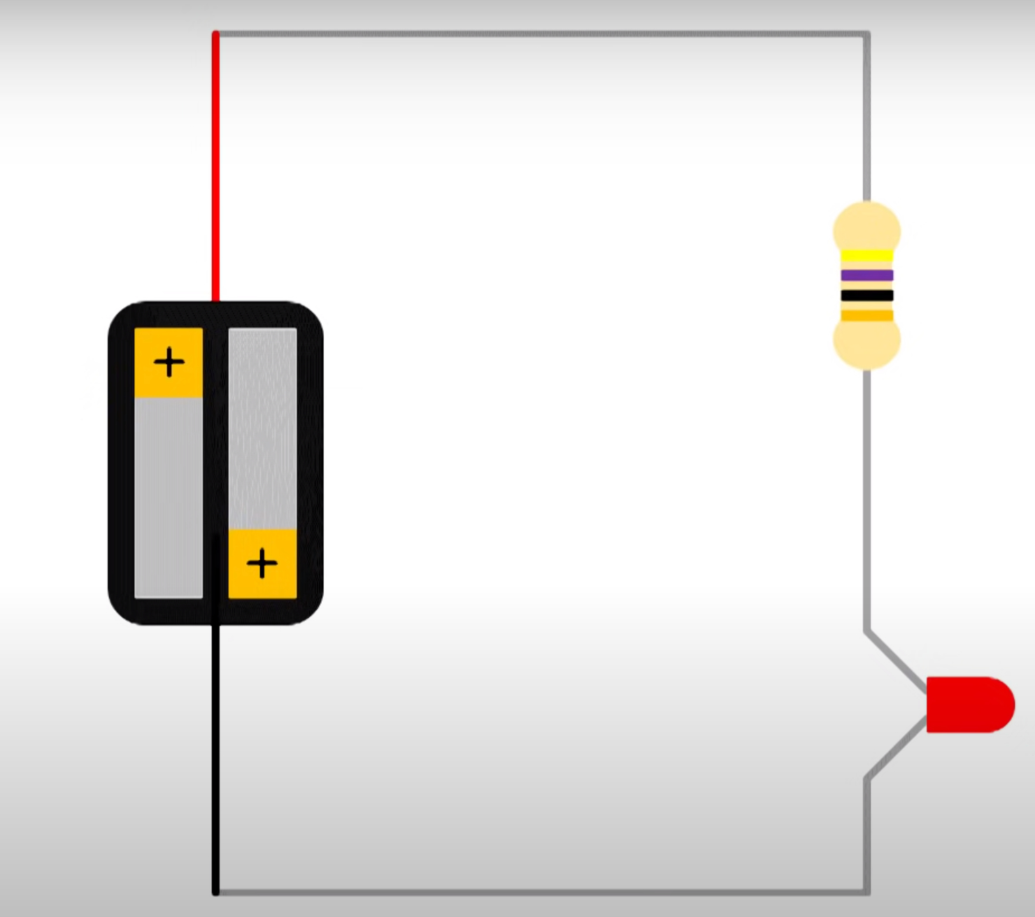
In circuit is said to be in series as one component follows another. We can measure the voltage across any one of the components individually. To measure you connect the multiimeter in parallel which means you put the probes either side of the component. This is said to be measuring in parallel. As usual the black goes to black (negative).
Example of measuring the voltage of the LED.
In our case they measured
- 2.83 battery
- 2.3 led
- 0.64 Resister
Which means the voltage of the led and resister = voltage of the battery.
Measuring Current of a Circuit
This will be the same where ever we measure for the circuit.
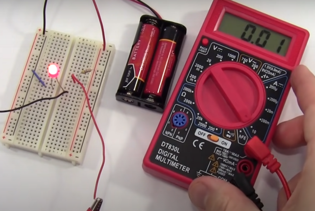
Key Points to measure Current
- Always set the meter back to volts when done because you might blow the fuse
- Always' use the top socket on the multimeter to start because you might blow the fuse
- To measure the current we need to add the probes in series
See the probes are added to the circuit.
Measuring Resistance
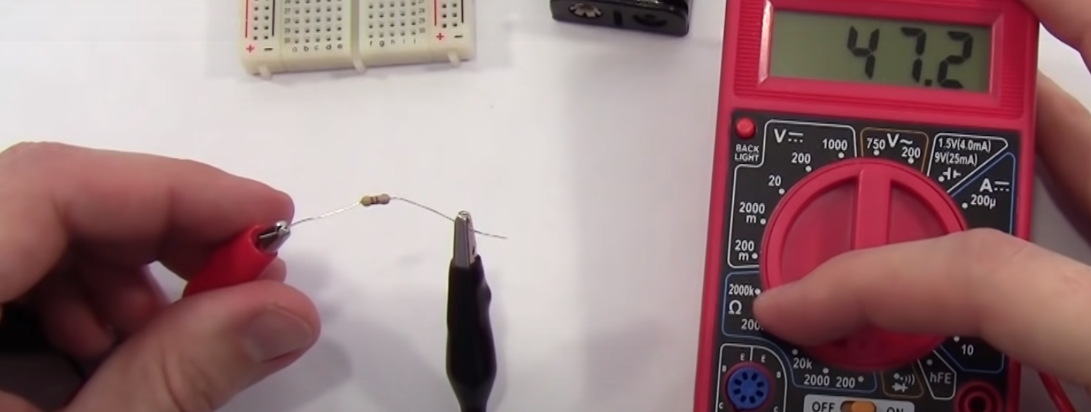
Set to Ω Ohms to measure resistance. Always measure unplugged and not in a live environment. Same as before. Set multimeter to Ohms and use the range appropriately.
Checking a Conductive Path
The final setting which looks like a diode beeps if there is a conductive path. We can now test the circuit to ensure that components are connected.
Breadboards
Origin
This comes from when they did use bread boards with screws in to make a circuit
Usage
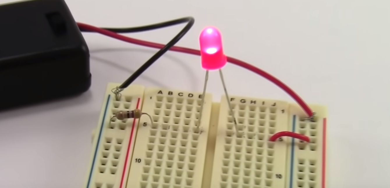
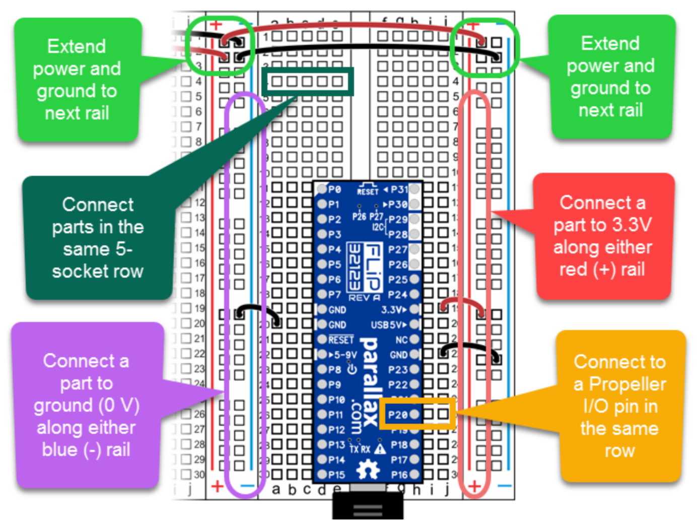
Basically they operate horizontally in the middle and vertically on the outside. Typically the outside rails are for the power supply.
Example Circuit=
We can see the ground is flowing vertically and the components are connected horizontally.
