Verilog: Difference between revisions
No edit summary |
|||
| Line 1: | Line 1: | ||
=Introduction= | =Introduction= | ||
Dipping my toe into this now I own an fpga | Dipping my toe into this now I own an fpga | ||
=Boolean Algebra= | =Boolean Algebra= | ||
Hardest thing about this is the amount of different symbols which mean the same thing.<br> | Hardest thing about this is the amount of different symbols which mean the same thing.<br> | ||
| Line 19: | Line 10: | ||
This was an alternative operators table where NOT uses a macron over the value to indicate inverted value.<br> | This was an alternative operators table where NOT uses a macron over the value to indicate inverted value.<br> | ||
[[File:Boolean notation.jpeg|400px]]<br> | [[File:Boolean notation.jpeg|400px]]<br> | ||
=Hello World= | |||
This is the first program. There are two files to get it to work, a pcf file which defines things you use in the verilog file. Currently my understanding is it maps hardware to names which you can reference in the verilog file. Here is the project. I only use two buttons in the example but there are four shown for the second example<br> | |||
[[File:Verilog1.jpg]] | |||
==Requirements | |||
For the requirements we have only light when both buttons are pressed. | |||
==Truth Table== | |||
We can express this as a circuit diagram and a truth table. We need to understand some boolean algebra to understand the truth table<br> | |||
[[File:Verilog hello world.jpeg]] | |||
==PCF Physical Constraints File== | ==PCF Physical Constraints File== | ||
Could not find a lexer but here we define names to io pins. You lookup the pin in the datasheet, in my case a ice40UP5K-B-EVN and you assign a name. | Could not find a lexer but here we define names to io pins. You lookup the pin in the datasheet, in my case a ice40UP5K-B-EVN and you assign a name. | ||
Revision as of 23:13, 21 January 2023
Introduction
Dipping my toe into this now I own an fpga
Boolean Algebra
Hardest thing about this is the amount of different symbols which mean the same thing.
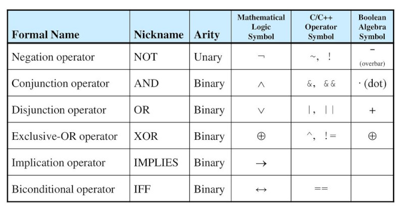
I guess each party wanted there own way. Here are the gates as seen on a circuit diagram
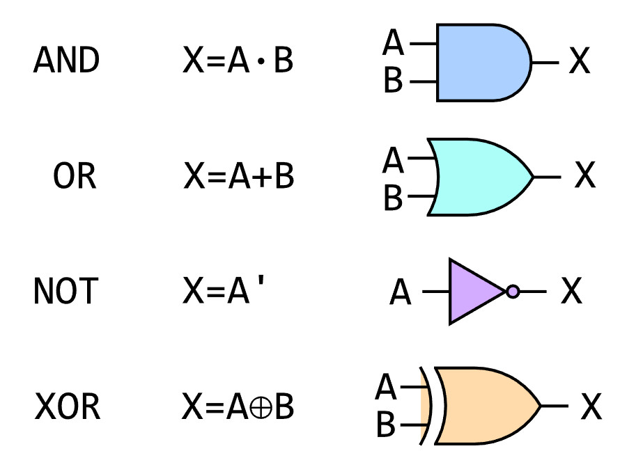
And of course someone else knew better. Here is IEEE version but given the amount of googling to get one nice enough I am guessing these are not popular

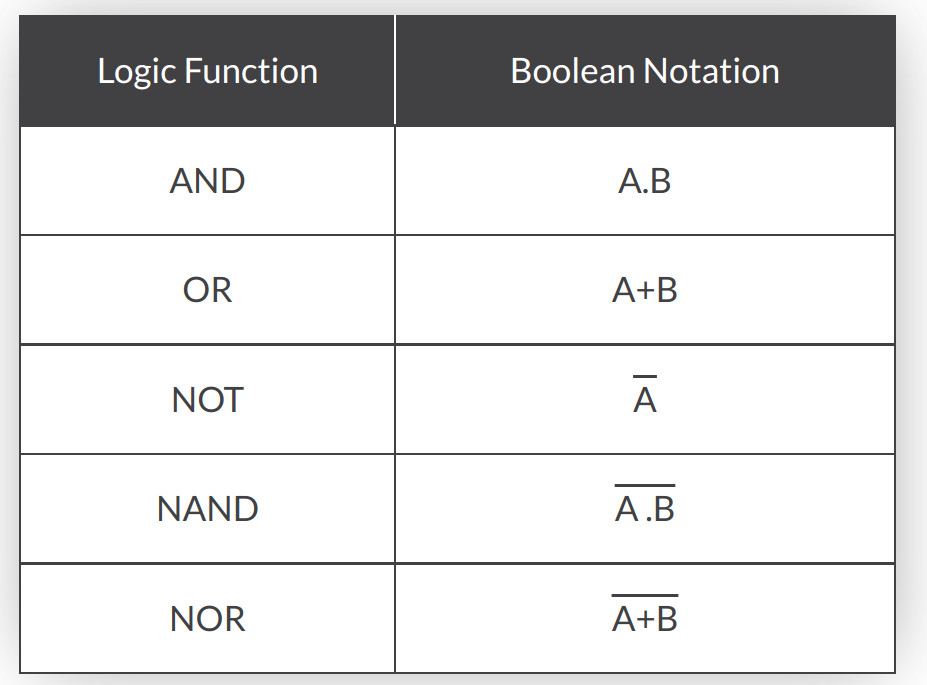
This was an alternative operators table where NOT uses a macron over the value to indicate inverted value.
Hello World
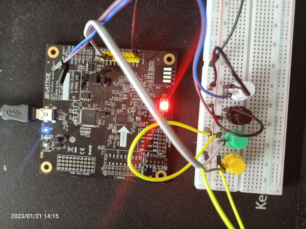
This is the first program. There are two files to get it to work, a pcf file which defines things you use in the verilog file. Currently my understanding is it maps hardware to names which you can reference in the verilog file. Here is the project. I only use two buttons in the example but there are four shown for the second example
 ==Requirements
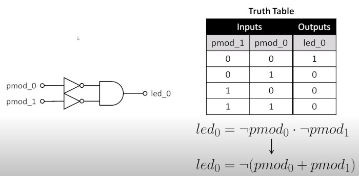
For the requirements we have only light when both buttons are pressed.
Truth Table
We can express this as a circuit diagram and a truth table. We need to understand some boolean algebra to understand the truth table
PCF Physical Constraints File
Could not find a lexer but here we define names to io pins. You lookup the pin in the datasheet, in my case a ice40UP5K-B-EVN and you assign a name.
#LED
set_io              led_0  41

#HEADER B I/O
set_io  -pullup yes pmod_0 23
set_io  -pullup yes pmod_1 25
Here is my first program, it defines two input buttons and 1 LED in a module called and_gate. The value of LED is true when pmod_0 and pmod_1 are true.
module and_gate (
    // inputs
    input   pmod_0,
    input   pmod_1,

    // Outputs
    output  led_0
);

    assign led_0 = ~pmod_0 & ~pmod_1;

endmodule