Raspberry Pico
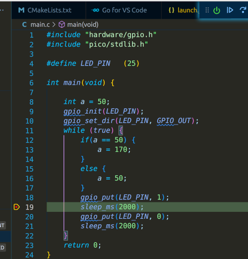
PICO Pinout
Always good to put at the top.
Introduction
Install the micro ros agent
sudo snap install micro-ros-agent
sudo snap set micro-ros-agent daemon=true
sudo systemctl restart snapd
Set up Environment Variables
Here are ones I use. I believe the build system rely on PICO_SDK_PATH and PICO_TOOLCHAIN_PATH
# Set up base directory
export PICO_ROOT=/home/$USER/dev/pico
export PICO_SDK_PATH=$PICO_ROOT/pico-sdk
export PICO_TOOLCHAIN_PATH=$PICO_ROOT/gcc-arm-none-eabi-10-2020-q4-major/bin
Get the compiler
This is how I got started.
Unzip and get the latest compiler from https://developer.arm.com/tools-and-software/open-source-software/developer-tools/gnu-toolchain/gnu-rm/downloads
I then extract it to $PICO_ROOT
Clone the SDK
Get the SDK
cd $PICO_ROOT
git clone --recurse-submodules https://github.com/raspberrypi/pico-sdk.git
git clone https://github.com/micro-ROS/micro_ros_raspberrypi_pico_sdk.git
Make the sample
It using CMake so we goto the source make a build directory and make. This should produce a file pico_micro_ros_example.uf2
cd $PICO_ROOT
cd micro_ros_raspberrypi_pico_sdk

mkdir build
cd build
cmake ..
make
Copy to device
So plug in the PICO holding down the boot button
cp pico_micro_ros_example.uf2 /media/$USER/RPI-RP2
Next
We can now look and see if the snap:pico slot is present with
snap interface serial-port
This did not work the first time and the slots: section was missing. I ended up rebooting the PICO, copying the file.
name:    serial-port
summary: allows accessing a specific serial port
plugs:
  - micro-ros-agent
slots:
  - snapd:pico (allows accessing a specific serial port)
New PICO Stuff
Spent lots of time doing lots of other stuff, ESP, learning React etc. Come back to PICO and this is note on this second view
Important
For a PICO to show up, you need to hold the BOOTSEL prior to plugging in the device. Release when powered and you should see
Bus 003 Device 004: ID 2e8a:0003 Raspberry Pi RP2 Boot
When you copy .uf2 software to the device /media/$USER/RPI-RP2/ the device will reboot and may or may not show up depending in what the software is. E.g.
cp ./blink.uf2 /media/$USER/RPI-RP2/

# No longer show device
# lsusb | grep 2e8a
# Disconnects but runs the software on the PICO (i.e. it starts blinking)
sudo dmesg

[80798.165244] FAT-fs (sdf1): unable to read boot sector to mark fs as dirty
Building MicroPython From Source
Revisiting build of this using the guild. Couple of glitches, repo was incorrect but this worked for me.
mkdir pico
cd pico
git clone  https://github.com/micropython/micropython
cd micropython/
cd lib/pico-sdk
git submodule update --init
# If required
# sudo apt install cmake gcc-arm-none-eabi build-essential
cd ../..
make -C mpy-cross
cd ports/rp2
make
Building picotool From Source
sudo apt install build-essential pkg-config libusb-1.0-0-dev
export PICO_SDK_PATH=/home/iwiseman/dev/projects/pico/pico/micropython/lib/pico-sdk

git clone https://github.com/raspberrypi/picotool
cd picotool
mkdir build
cd build
cmake ..
make
# optional
sudo cp /home/$USER/dev/projects/pico/pico/picotool/build/picotool /usr/bin/picotool
Using Ros 2 and Pico
- Followed the instructions for https://ubuntu.com/blog/getting-started-with-micro-ros-on-raspberry-pi-pico and managed to get this to work.
- Installed ROS on ubuntu 22.04 using https://docs.ros.org/en/rolling/Installation/Ubuntu-Install-Debians.html
This is important because I could not get the Pico to create a /dev/ttyACM0
Pico-Exampleas
Building
This took some time because I tried to build the examples individually.
# Clone and build
git clone https://github.com/raspberrypi/pico-examples
cd pico-examples
makedir build
cd build
cmake ..
make
Doing this with just an one example e.g.
cd hello_world/
mkdir build
cd build/
cmake ..
Results in the following error
CMake Warning (dev) in CMakeLists.txt:
  No project() command is present.  The top-level CMakeLists.txt file must
  contain a literal, direct call to the project() command.  Add a line of
  code such as

    project(ProjectName)

  near the top of the file, but after cmake_minimum_required().

  CMake is pretending there is a "project(Project)" command on the first
  line.
This warning is for project developers.  Use -Wno-dev to suppress it.

CMake Error at serial/CMakeLists.txt:9 (pico_add_extra_outputs):
  Unknown CMake command "pico_add_extra_outputs".
Serial vs USB
They look the same but they are not. Here is the difference in the USB makefiles
    # enable usb output, disable uart output
    pico_enable_stdio_usb(hello_usb 1)
    pico_enable_stdio_uart(hello_usb 0)
C++ Example
Create demo program
#include <stdio.h>
#include <pico/stdlib.h>

int main()
{
    stdio_init_all();

    while (true) {
        printf("Hello world\n");
        sleep_ms(1000);
    }
}
And a CMakefile
cmake_minimum_required(VERSION 3.13)

include($ENV{PICO_SDK_PATH}/external/pico_sdk_import.cmake)

project(myapp C CXX ASM)

set(CMAKE_C_STANDARD 11)
set(CMAKE_CXX_STANDARD 17)

pico_sdk_init()

add_executable(${PROJECT_NAME} main.c)

pico_add_extra_outputs(${PROJECT_NAME})

target_link_libraries(${PROJECT_NAME} pico_stdlib)

pico_enable_stdio_usb(${PROJECT_NAME} 1)
pico_enable_stdio_uart(${PROJECT_NAME} 0)
Create a build directory and build
mkdir build
cd build
cmake ..
make -j$(nproc)
Copying the software to the Pico and monitoring with screen gives
cp myapp.uf2  /media/iwiseman/RPI-RP2/

sudo screen /dev/ttyACM0 115200

Hello world
Hello world
Hello world
....
# CTRL+A \ to exit
LAN8720
Put this up to remind me of my wiring it will be different next time. I like the groupings
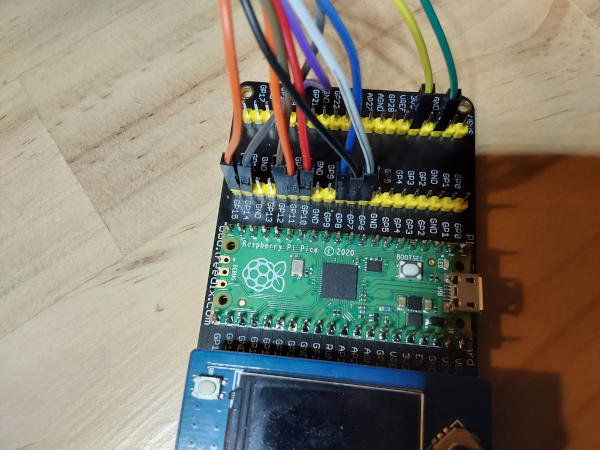
- Yellow VCC 3V3
- Green GND GND
- Purple nInt GP20
- Red TX0 GP10
- Orange 1 TX1 GP11
- Brown TX_EN GP12
- White RX0 GP6
- Black RX1 GP7
- Blue CRS GP8
- Grey MDIO GP14
- Orange 2 MDC GP15
PIO and the PICO
Sounds like a new book but this is reminding myself of the old C64 and assembly. Starting with the blink project and reading until tired.
Blink
Prerequisites
We need to have a working PICO sdk mine is in
PICO_SDK_PATH=/opt/pico/pico-sdk
CMake file
For CMake I have cmake 3.22.1
# Set minimum required version of CMake
cmake_minimum_required(VERSION 3.12)

# Include build functions from Pico SDK
include($ENV{PICO_SDK_PATH}/external/pico_sdk_import.cmake)
include($ENV{PICO_SDK_PATH}/tools/CMakeLists.txt)

# Set name of project (as PROJECT_NAME) and C/C   standards
project(blink C CXX ASM)
set(CMAKE_C_STANDARD 11)
set(CMAKE_CXX_STANDARD 17)

# Creates a pico-sdk subdirectory in our project for the libraries
pico_sdk_init()

# Tell CMake where to find the executable source file
add_executable(${PROJECT_NAME}
    src/main.c
)

# Create C header file with the name <pio program>.pio.h
pico_generate_pio_header(${PROJECT_NAME}
        ${CMAKE_CURRENT_LIST_DIR}/src/blink.pio
)

# Create map/bin/hex/uf2 files
pico_add_extra_outputs(${PROJECT_NAME})

# Link to pico_stdlib (gpio, time, etc. functions)
target_link_libraries(${PROJECT_NAME}
    pico_stdlib
    hardware_pio
)

# Enable usb output, disable uart output
pico_enable_stdio_usb(${PROJECT_NAME} 0)
pico_enable_stdio_uart(${PROJECT_NAME} 1)
C Code
Nothing special here
#include <stdio.h>
#include <stdbool.h>
#include <pico/stdlib.h>
#include <hardware/pio.h>
#include <blink.pio.h>

#define LED_BUILTIN 25

int main() {
  stdio_init_all();

  PIO pio = pio0;
  uint state_machine_id = 0;
  uint offset = pio_add_program(pio, &blink_program);

   blink_program_init(pio, state_machine_id, offset, LED_BUILTIN);

  while(1) {
    //do nothing
  }
}
PIO Code
This is the C64 bit you make a file call blink.pio which contains assembly and C-SDK bindings which seem like a bit of voodoo and hope to learn more. The assembly is straight forward.
.program blink

set pindirs, 1      ; Set pin to output
loop:
  set pins, 1 [31]  ; Drive pin high and then delay for 31 cycles
  set pins, 0 [31]  ; Drive pin low and then delay for 31 cycles
  jmp loop

% c-sdk {

static inline void blink_program_init(PIO pio, uint sm, uint offset, uint pin) {

  // 1. Define a config object
  pio_sm_config config = blink_program_get_default_config(offset);

  // 2. Set and initialize the output pins
  sm_config_set_set_pins(&config, pin, 1);

  // 3. Apply the configuration & activate the State Machine
  pio_sm_init(pio, sm, offset, &config);
  pio_sm_set_enabled(pio, sm, true);
}

%}
Breakdown of PIO Instructions
The SDK provides
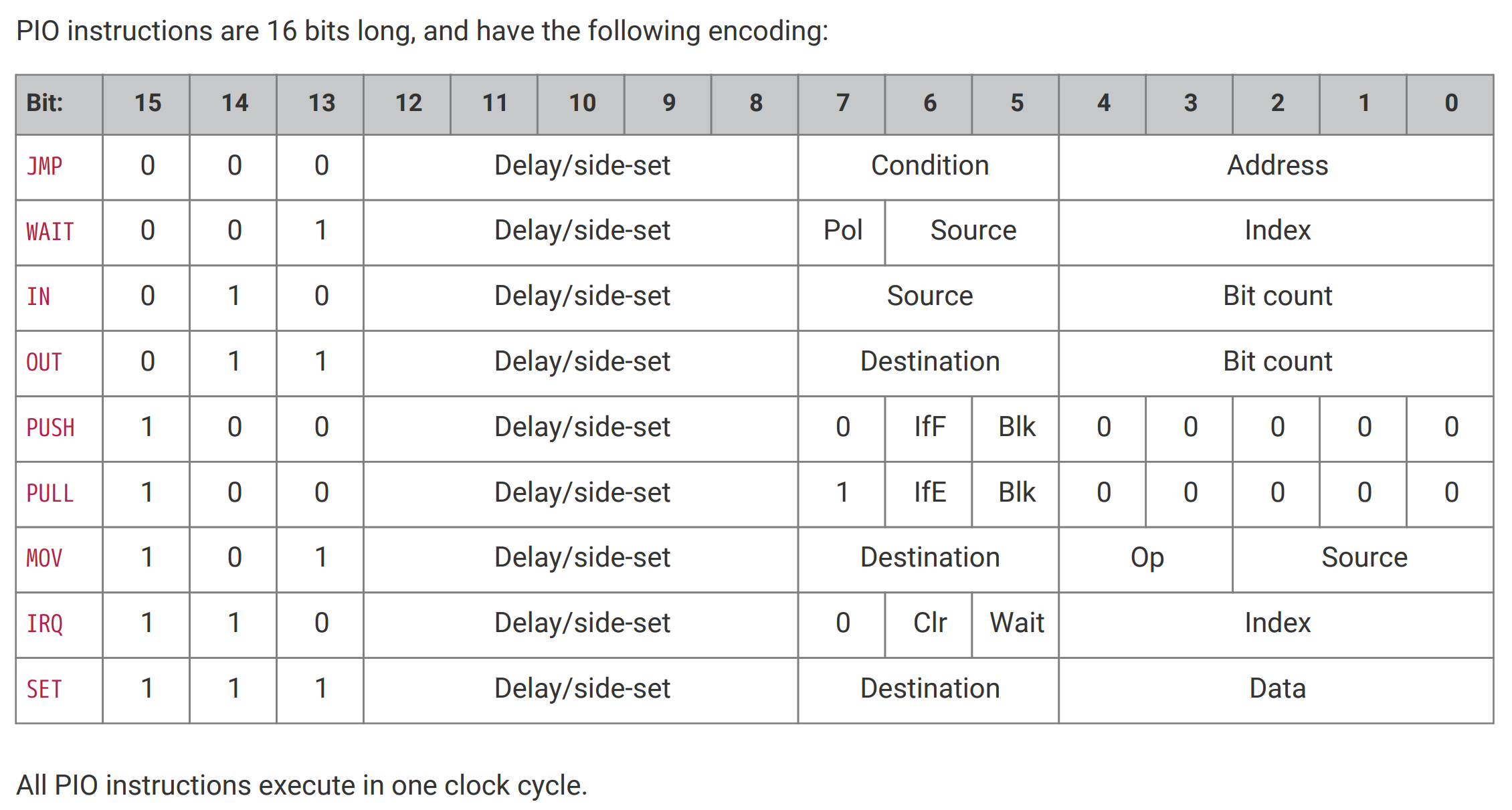 Sebastian Günther breaks this down as
Program Structure
To structure your program in general, you have the following commands available.
- .program NAME - the name of the program, and also the name of the header file that will be generated during compilation to give you access to the state machine in your main program
.define NAME VALUE - similar to your C program, you can define top-level constants that are visible in the state machine
- LABEL: - labels are syntactic grouping of related statements. You can define any label, and then jump back to it
- ; COMMENT - Anything behind a semicolon is a comment
- .wrap_target and .wrap - Instructions to repeatedly run a section of you PIO program
- .word - Store a raw 16-bit value as instructions in the program (each PIO statement is a 16-bit value)
- .side_set COUNT (opt) - This instruction additionally configures the SIDE pins of this program. The COUNT value is the number of bits that is reduced from the instruction, and the opt value determines whether side statements inside your PIO program are optional or mandatory. When you work with this declaration, then you can attach additional commands to all expressions, for example out x, 1 side 0 would shift one bite from the OSR to the FIFO RX, and set the SIDE pin to logic level LOW.
Move data inside the shift register
- in SOURCE count - Shift data into the ISR, where SOURCE can be X, Y, OSR or ISR, and count is 0...32
- out DESTINATION count - Shift data out of the OSR, to DESTINATION X, Y, ISR
- mov DESTINATION, SOURCE - Move data from SOURCE (X, Y, OSR or ISR) to DESTINATION (X, Y, OSR or ISR)
- set DESTIANTION, data - write a 5-bit data value to DESTIANTION (X, Y)
Move data between the shift register and the main program
- pull - Load data from the TX FIFO into the OSR
- push - Push data from the ISR to the RX FIFO, then clear the ISR
- irq INDEX op - Modify the IRQ number index to be either cleared (op=0) or set (op=1)
Write data to GPIO pins
- SET pins
- set PINDIRS, 1 - define the configured SET pins as output pins
- set PINS, value - write HIGH (value=1) or LOW (value=1) to the SET pins
- OUT pins
- mov PINS, SOURCE - write from SOURCE (X, Y, OSR, ISR) to OUT pins (X, Y, OSR or ISR)
Read data from GPIO pins
- SET pins
- set PINDIRS, 0 - define the configured SET pins as input pins
- INPUT pins
- mov DESTINATION, PINS - write from IN pins to DESTINATION (X, Y, OSR, ISR, and OUT PINS)
Conditional Statements
- jmp CONDITION LABEL - go to LABEL when one the following type of CONDITION is true
- !(X|Y|OSRE) - true when X, Y, OSR is empty
- X-- | Y--) - true when scratch register is empty, otherwise decrement the scratch register
- PIN - true when the JUMP pin is logic level HIGH
- wait POLARITY TYPE NUMBER - delay the further processing until the POLARITY matches the ..
- pin NUMBER - INPUT pin
- gpio NUMBER - absolutely numbered gpio
- irq NUMBER - IRQ number (if POLARITY is 1, the IRQ number is cleared)
- nop - Don’t do anything
Vodoo Part
Thanks again to Sebastian Günther here is a list of configurations you might like to use. Maybe I will uncover what these all mean as I go on my journey.
static inline void __program_init(PIO pio, uint sm, uint offset, uint in_pin, uint in_pin_count, uint out_pin, uint out_pin_count, float frequency) {

  // 1. Define a config object
  pio_sm_config config = __program_get_default_config(offset);

  // 2. Set and initialize the input pins
  sm_config_set_in_pins(&config, in_pin);
  pio_sm_set_consecutive_pindirs(pio, sm, in_pin, in_pin_count, 1);
  pio_gpio_init(pio, in_pin);

  // 3. Set and initialize the output pins
  sm_config_set_out_pins(&config, out_pin, out_pin_count);
  pio_sm_set_consecutive_pindirs(pio, sm, out_pin, out_pin_count, 0);

  // 4. Set clock divider
  if (frequency < 2000) {
    frequency = 2000;
  }
  float clock_divider = (float) clock_get_hz(clk_sys) / frequency * 1000;
  sm_config_set_clkdiv(&config, clock_divider);

  // 5. Configure input shift register
  // args: BOOL right_shift, BOOL auto_push, 1..32 push_threshold
  sm_config_set_in_shift(&config, true, false, 32);

  // 6. Configure output shift register
  // args: BOOL right_shift, BOOL auto_push, 1..32 push_threshold
  sm_config_set_out_shift(&config, true, false, 32);

  // 7. Join the ISR & OSR
  // PIO_FIFO_JOIN_NONE = 0, PIO_FIFO_JOIN_TX = 1, PIO_FIFO_JOIN_RX = 2
  sm_config_set_fifo_join(&config, PIO_FIFO_JOIN_NONE);

  // 8. Apply the configuration
  pio_sm_init(pio, sm, offset, &config);

  // 9. Activate the State Machine
  pio_sm_set_enabled(pio, sm, true);
}
PICO W
First foray into the pico W. Three things I initially had trouble with
- turn on the serial ports or you don't have /dev/ttyACM0
- make sure PICO_BOARD set correctly
- make sure you copy a cmake that works. Mine was [here]
New Project
You need to copy these files before you start a project. Note
cp /opt/pico/pico-examples/pico_w/lwipopts_examples_common.h lwipopts.h
cp /opt/pico/pico-examples/pico_w/blink/CMakeLists.txt .
CMAKE
And here is the CMAKE.
cmake_minimum_required(VERSION 3.13)

include(pico_sdk_import.cmake)

project(pico-cpp C CXX)

SET(PICO_BOARD pico_w)
set(CMAKE_C_STANDARD 11)
set(CMAKE_CXX_STANDARD 17)

# initialize the Raspberry Pi Pico SDK
pico_sdk_init()

add_executable(pico-cpp src/main.cpp)

pico_add_extra_outputs(pico-cpp)

pico_enable_stdio_usb(pico-cpp 1)
pico_enable_stdio_uart(pico-cpp 1)

target_include_directories(pico-cpp PRIVATE ${CMAKE_CURRENT_LIST_DIR} )

target_link_libraries(pico-cpp pico_cyw43_arch_lwip_threadsafe_background pico_stdlib)
Code
#include <stdio.h>
#include "pico/stdlib.h"
#include "pico/cyw43_arch.h"

char ssid[] = "YOUR_SID";
char pass[] = "YOUR_PASSWORD";

int main() {
  printf("Iain was ere\n");

  stdio_init_all();

  if (cyw43_arch_init_with_country(CYW43_COUNTRY_UK)) {
    printf("failed to initialise\n");
    return 1;
  }
  printf("initialised\n");

  cyw43_arch_enable_sta_mode();

  if (cyw43_arch_wifi_connect_timeout_ms(ssid, pass, CYW43_AUTH_WPA2_AES_PSK, 10000)) {
    printf("failed to connect\n");
    return 1;
  }
  printf("connected\n");
}
Debugging With J-Link
Using the command line
Took a weekend to get this going and still need to improve. Using a standard Pico I wired up a J-Link v9.
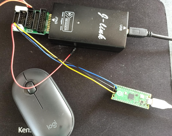
Eventually found that the pico needed a really good connection to work. When it failed the message was
Info : 240 18 arm_dap.c:337 handle_dap_init(): DAP init failed
Debug: 241 18 command.c:628 run_command(): Command 'dap init' failed with error code -4
So once I have built openocd from the raspberrypi branch using
git clone https://github.com/raspberrypi/openocd.git --depth=1 --no-single-branch
cd openocd
./bootstrap
./configure --enable-picoprobe ①
make -j4
We can upload myProject.elf to the pico with
openocd -s ~/dev/projects/pico/openocd/tcl -f interface/jlink.cfg -c "transport select swd" -c "adapter_khz 4000" -f target/rp2040.cfg -c "program myProject.elf verify reset exit"
To start openocd
openocd -s ~/dev/projects/pico/openocd/tcl -f interface/jlink.cfg -c "transport select swd" -c "adapter_khz 6000" -f target/rp2040.cfg -c "init; reset;"
This is what good looks like
Open On-Chip Debugger 0.11.0-g4f2ae61 (2022-11-13-18:17)
Licensed under GNU GPL v2
For bug reports, read
	http://openocd.org/doc/doxygen/bugs.html
swd
DEPRECATED! use 'adapter speed' not 'adapter_khz'
adapter speed: 6000 kHz

Info : Hardware thread awareness created
Info : Hardware thread awareness created
Info : RP2040 Flash Bank Command
Info : J-Link V9 compiled May  7 2021 16:26:12
Info : Hardware version: 9.60
Info : VTarget = 3.329 V
Info : clock speed 6000 kHz
Info : SWD DPIDR 0x0bc12477
Info : SWD DLPIDR 0x00000001
Info : SWD DPIDR 0x0bc12477
Info : SWD DLPIDR 0x10000001
Info : rp2040.core0: hardware has 4 breakpoints, 2 watchpoints
Info : rp2040.core1: hardware has 4 breakpoints, 2 watchpoints
Info : starting gdb server for rp2040.core0 on 3333
Info : Listening on port 3333 for gdb connections
Info : SWD DPIDR 0x0bc12477
Info : SWD DLPIDR 0x00000001
Info : Listening on port 6666 for tcl connections
Info : Listening on port 4444 for telnet connections
On a separate terminal start the debugger with
gdb-multiarch myProject.elf
target remote localhost:3333
Remote debugging using localhost:3333
warning: multi-threaded target stopped without sending a thread-id, using first non-exited thread
Note: automatically using hardware breakpoints for read-only addresses.
time_reached (t=...)
    at /opt/pico/pico-sdk/src/rp2_common/hardware_timer/include/hardware/timer.h:116
116	    uint32_t hi_target = (uint32_t)(target >> 32u);
(gdb) load
Loading section .boot2, size 0x100 lma 0x10000000
Loading section .text, size 0x4060 lma 0x10000100
Loading section .rodata, size 0xe2c lma 0x10004160
Loading section .binary_info, size 0x1c lma 0x10004f8c
Loading section .data, size 0x1ac lma 0x10004fa8
Start address 0x100001e8, load size 20820
Transfer rate: 23 KB/sec, 3470 bytes/write.
(gdb) c
Continuing.
target halted due to debug-request, current mode: Thread
xPSR: 0x01000000 pc: 0x0000012a msp: 0x20041f00

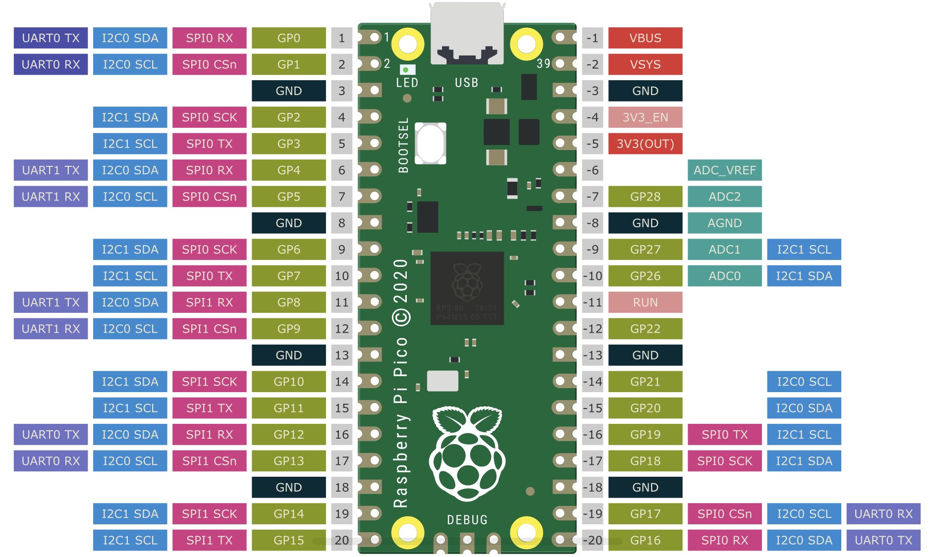
Thread 1 hit Breakpoint 1, main () at /home/iwiseman/dev/projects/pico/jtag/main.c:19
19	        sleep_ms(2000);
(gdb) p a
$1 = 170
(gdb) c
Continuing.
target halted due to debug-request, current mode: Thread
xPSR: 0x01000000 pc: 0x0000012a msp: 0x20041f00

Thread 1 hit Breakpoint 1, main () at /home/iwiseman/dev/projects/pico/jtag/main.c:19
Using VSCode
C++ Config
Add this to settings.json makes the include issues disappear for me using CMake
{
    "C_Cpp.default.configurationProvider": "ms-vscode.cmake-tools"
}
Jlink
Again, never easy, but got it to work. Looking at the above there are two commands run between the interface and the target of the openocd command.
openocd -s ~/dev/projects/pico/openocd/tcl -f interface/jlink.cfg -c "transport select swd" -c "adapter_khz 4000" -f target/rp2040.cfg -c "program myProject.elf verify reset exit"
It is apparently important the order of the arguments. So to get this to work these two commands need to run before rp2040.cfg. So to make this work you just edit the rp2040.cfg file and add these at the top.
transport select swd
adapter_khz 6000

source [find target/swj-dp.tcl]
source [find mem_helper.tcl]

set _CHIPNAME rp2040
set _CPUTAPID 0x01002927
set _ENDIAN little

swj_newdap $_CHIPNAME.core0 cpu -dp-id $_CPUTAPID -instance-id 0
swj_newdap $_CHIPNAME.core1 cpu -dp-id $_CPUTAPID -instance-id 1
....
So now we can run the debugger within vscode. You will need to amend you parameters appropriately. I copy the openocd and cp -rp the tcl directory.
{
  "version": "0.2.0",
  "configurations": [
    {
      "name": "openocd",
      "request": "launch",
      "type": "cortex-debug",
      "gdbPath" : "gdb-multiarch",
      "cwd": "${workspaceRoot}",
      "interface": "swd",
      "runToMain": true,
      "servertype": "openocd",
      "serverpath": "/opt/openocd/pico/bin/openocd",
      "executable": "${workspaceRoot}/build/myProject.elf",
      "searchDir": ["/opt/openocd/pico/tcl"],
      "preLaunchCommands": ["set mem inaccessible-by-default off"],
      "configFiles": ["interface/jlink.cfg","target/rp2040.cfg",],
      "showDevDebugOutput": false,
    }
  ]
}
PicoProbe
This was the next attempt. For this approach we use the debugger externally. Make openocd in the normal way and from the root directory
export PATH=/home/iwiseman/dev/projects/rust/openocd/src:$PATH
src/openocd   -f interface/picoprobe.cfg -f target/rp2040.cfg -s tcl
Good output looks like this
Open On-Chip Debugger 0.11.0-g4f2ae61 (2022-12-25-15:22)
Licensed under GNU GPL v2
For bug reports, read
	http://openocd.org/doc/doxygen/bugs.html
Info : only one transport option; autoselect 'swd'
adapter speed: 5000 kHz
Info : Hardware thread awareness created
Info : Hardware thread awareness created
Info : RP2040 Flash Bank Command
Info : Listening on port 6666 for tcl connections
Info : Listening on port 4444 for telnet connections
Info : clock speed 5000 kHz
Info : SWD DPIDR 0x0bc12477
Info : SWD DLPIDR 0x00000001
Info : SWD DPIDR 0x0bc12477
Info : SWD DLPIDR 0x10000001
Info : rp2040.core0: hardware has 4 breakpoints, 2 watchpoints
Info : rp2040.core1: hardware has 4 breakpoints, 2 watchpoints
Info : starting gdb server for rp2040.core0 on 3333
Info : Listening on port 3333 for gdb connections
For vs code you need to use cortex debug and here is the launch.json
{
  // Use IntelliSense to learn about possible attributes.
  // Hover to view descriptions of existing attributes.
  // For more information, visit: https://go.microsoft.com/fwlink/?linkid=830387
  "version": "0.2.0",
  "configurations": [
    {
      "name": "Debug rp2040-project-template",
      "request": "launch",
      "type": "cortex-debug",
      "cwd": "${workspaceRoot}",
      "executable": "${workspaceFolder}/build/mma845.elf",
      "servertype": "external",
      "gdbPath": "gdb-multiarch",

      // Connect to an already running OpenOCD instance
      "gdbTarget": "localhost:3333",

      "svdFile": "${env:PICO_SDK_PATH}/src/rp2040/hardware_regs/rp2040.svd",
      "runToEntryPoint": "main",
      "preLaunchCommands": [
        "monitor init",
        "monitor reset init",
        "monitor halt"
      ],
      // Work around for stopping at main on restart
      "postRestartCommands": [
        "break main",
        "continue",
        "help",
        "help",
        "clear main"]
    }
  ]
}
