Boolean Algebra
Introduction
This is an introduction to boolean algebra
FRED
This is text
Symbols (crash)
One of the hardest thing about boolean algebra is that it is used in Computer Science, Electronics and Maths. As such there is different notations but mean the same thing.
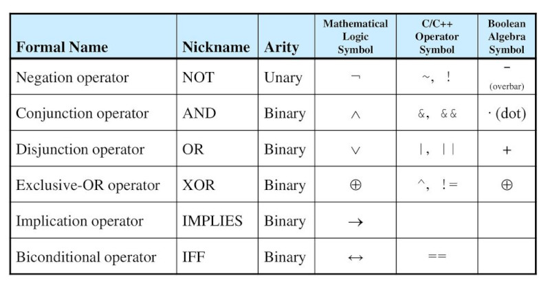
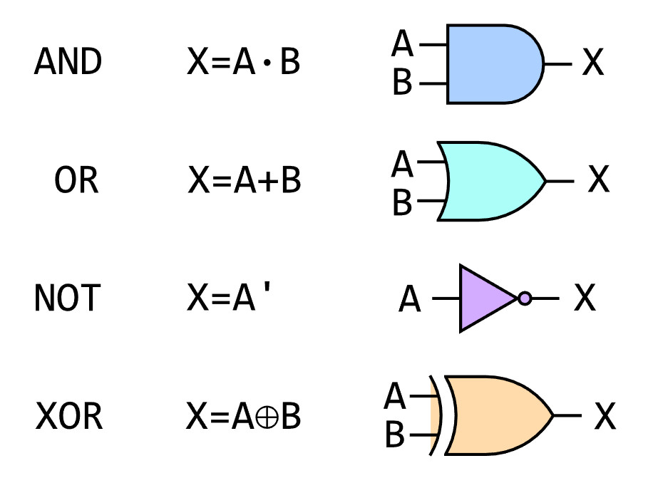
I guess each party wanted there own way. Here are the gates as seen on a circuit diagram
And of course someone else knew better. Here is IEEE version but given the amount of googling to get one nice enough I am guessing these are not popular

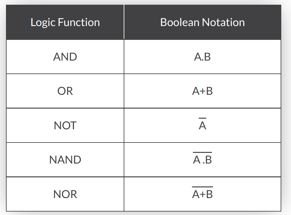
This seemed to be the popular way for documentr a truth table where NOT uses a macron over the value to indicate inverted (negated) value.
Order of Presidence
In regular maths we have PEMDAS for order of presidence apparantely which means
- P Parentheses first
- E Exponents (ie Powers and Square Roots, etc.)
- MD Multiplication and Division (left-to-right)
- AS Addition and Subtraction (left-to-right)
For Boolean Algebra we just have
- P Parentheses first e.g. ()
- I Inverses e.g. C̅.C̅
- P Products (.)
- S Sums (+)
Truth Tables and Gates
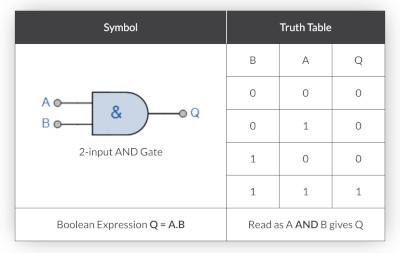
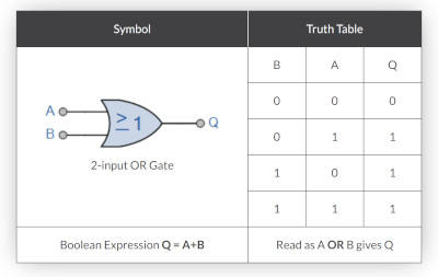
Here are all of the gates. We can see boolean expression and equivalents in the diagrams along with the truth tables.
AND Gate
Here is the AND gate and truth table.
OR Gate
Here is the OR Gate and Truth table
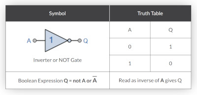
NOT Gate
Here is the NOT Gate and Truth table
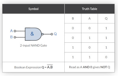
NAND Gate
Here is the NAND Gate and Truth Table
NOR Gate
And here is the NOR gate equivalent. It really is not as hard as it looks once you are in the zone. Right the truth table and the algebra and ezzy pezzy.
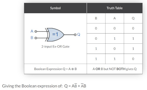
XOR Gate
I write this not in order. But further down I struggled with the boolean algebra for XOR gates and the substitution. Below is the explanation for which it works. Here is the truth table
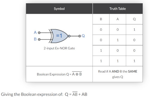
Exclusive XNOR Gate
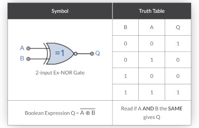
Here is the Exclusive NOR Gate and truth table
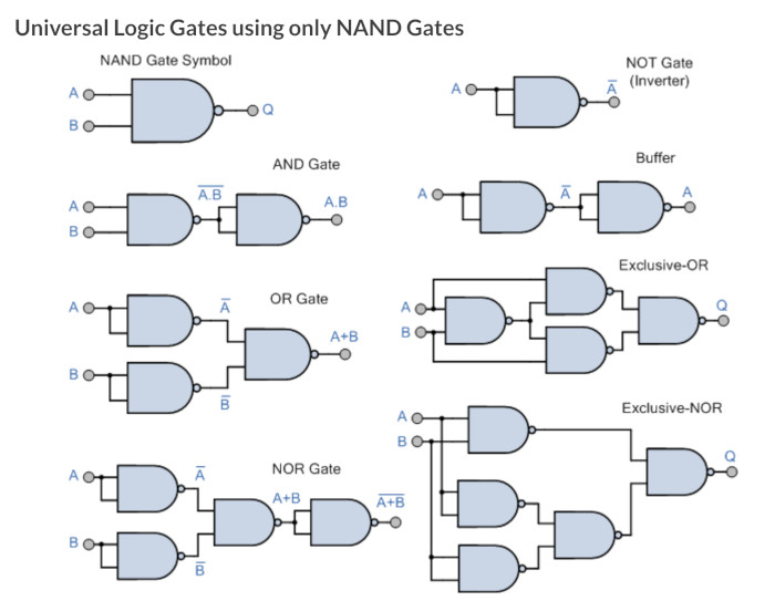
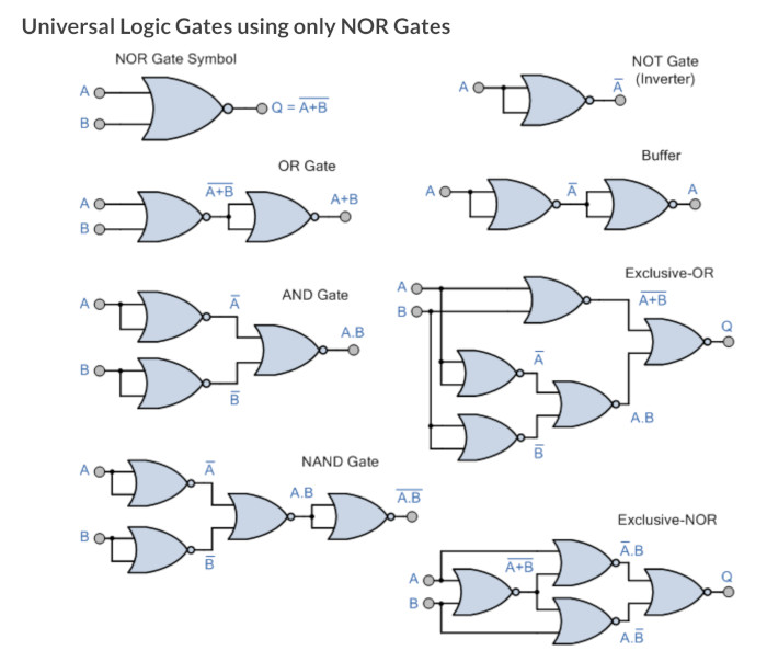
Universal Gates
During the demonstration of using the De Morgon theorems, it was shown that you can make any gate from either NAND or NOR gates so thought I might put these here.
Proving Gates
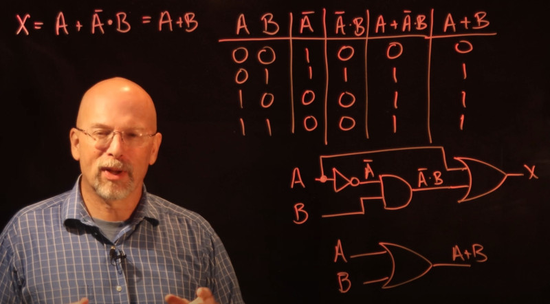
In the youtube by Intermation they prove one of the expression equals another. And also shows
- Expression to prove
- Truth Table for expression and how to build it
- Physical Representation
He summarises that rationalisation reduces the power, increases the speed and reduces the cost and space.
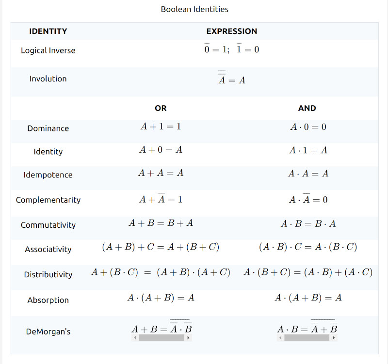
Identities Of Boolean
A new new phrase for me to google but this is about how to calculate result when a value is ANDed or ORed with itself for example. Not Shown in the slide but here is the XOR examples A⊕A examples
- A ⊕ A = 0 With Self
- A ⊕ A̅ = 1 With Inverse
- A ⊕ 1 = A̅ With 1
- A ⊕ 0 = 1 With 0
So watching the video finally ties up the phrases
- Idempotence = Wth Self =
- Complementarity = With Inverse
- Dominance = With 1
- Identity = With 0
Boolean Laws
Commutative Law
Any binary operation which satisfies the following expression is referred to as a commutative operation. Commutative law states that changing the sequence of the variables does not have any effect on the output of a logic circuit.
- A. B = B. A
- A + B = B + A
Associative Law
It states that the order in which the logic operations are performed is irrelevant as their effect is the same.
- ( A. B ). C = A . ( B . C )
- ( A + B ) + C = A + ( B + C)
Distributive Law
Distributive law states the following conditions:
- A. ( B + C) = (A. B) + (A. C)
- A + (B. C) = (A + B) . ( A + C)
AND Law
These laws use the AND operation. Therefore they are called AND laws.
- A .0 = 0
- A . 1 = A
- A. A = A
OR Law
These laws use the OR operation. Therefore they are called OR laws.
- A + 0 = A
- A + 1 = 1
- A + A = A
Inversion Law
In Boolean algebra, the inversion law states that double inversion of variable results in the original variable itself.
Boolean Algebra Theorems
De Morgan’s First Law
De Morgan’s First Law states that the complement of the product of the variables is equal to the sum of their individual complements of a variable.
(A.B)’ = A’+B’
or
¬(A.B) = ¬A + ¬B
or
¬(A AND B) = ¬A OR ¬B
De Morgan’s Second Law
The second law states that the complement of the sum of variables is equal to the product of their individual complements of a variable.
(A+B)’ = A’.B’
or
¬(A+B) = ¬A . ¬B
or
¬(A OR B) = ¬A AND ¬B
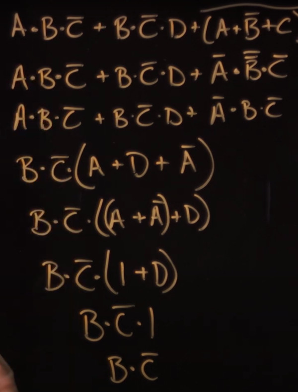
Boolean Algebra Example Simplification
All the time we are looking for something
- being combined with itself
- being combined with its inverse
- being combined with a constant
Example 1
=> A+ A.B
=> A.1 + A.B // A.1 = A See Identifies above
=> A.(1+B)   // Pulling out A a common to both
=> A.1
=> A
Example 2
A + A̅.B
=> (A + A̅).(A + B) //  distributive law A + B . C = (A + B).( A + C)
=> 1.(A + B)       //  A + A̅ = 1
=> A + B           // 1.anything = anything
Example
Final example
- Step 1 De Morgans Theorem
Sum Of Products
Used the Youtube examle. This
- Creates an initial truth table we create
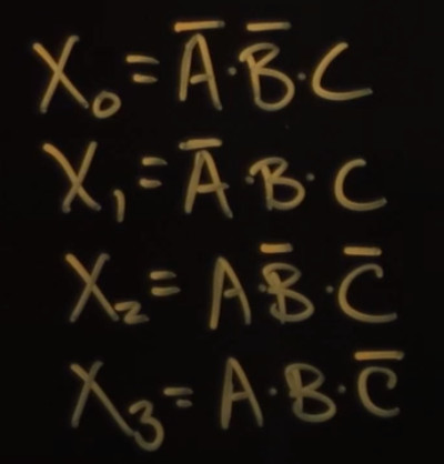
- For each X with a 1 we want make a column and name it
- Write Expression for each Column
- Simplify Algebra expressions
- Becomes a Physical Circuit
Create an initial truth table we create
We make our requirement for X which could be anything
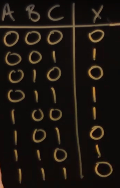
For each X with a 1 we want make a column and name it
We have labelled each column and will write the express for it
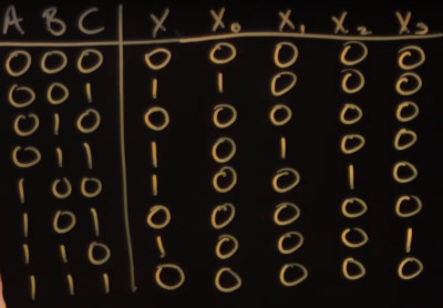
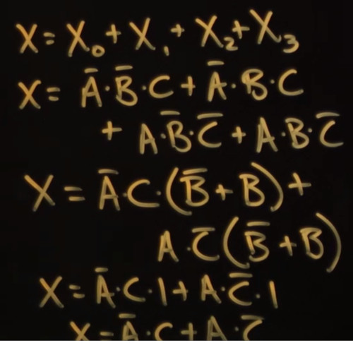
Write Expression for each Column
Simplify Algebra expressions
Cannot may read this but we can get the idea
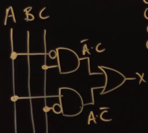
Becomes a Physical Circuit
The final step. This is an excellent walk through from the start of learning Boolean Algebra to the actual point of it. The method of diagramming is called Bus Notation.
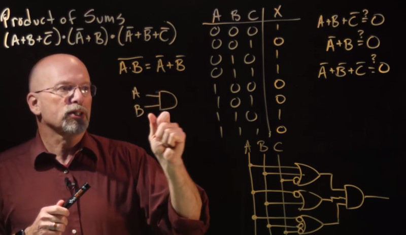
Product of Sums
We can do the same with this as we did with sum of products. Below shows a worked example where three sums +, are added together
Karnaugh Maps
Struggled with three versions of this to understand what was going on so here goes my attempt to document
What are they for
They are an approach to simplify boolean algebra without having to remember all of the laws an theorems by using a graphical approach. E.g. in the truth adder for Verilog we need to solve this.
(A̅.B̅.C ) + (A̅.B.C̅) + (A.B̅.C̅) + (A.B.C)
Lets take C as common and pair up with 1st and 4th expression and 2 and 3 => C ( A̅.B̅ + A.B ) + C̅ (A̅.B + A.B̅)
Found this a bit tricky to wrote up the XOR and NOR above. Basically A̅.B̅ + A.B = A̅ ⊕ B̅ - XOR and A̅.B + A.B̅ = A ⊕ B - NOR => C ( A̅ ⊕ B̅ ) + C̅ ( A ⊕ B)
Lets substitute A̅ ⊕ B̅ = x this gives => Cx̅ + C̅x Compliments result in XOR => C ⊕ x
Substituting x back in
=> C ⊕ A ⊕ B
Prerequisites
We clearly need to understand truth tables and what boolean logic is. We also need to understand a bit (no pun intended) about Gray Code.
Making a Map
The first thing we need to understand is how to map an truth table to a K-Map (Karnaugh Map). This is actually straight for except for we need to have knowledge of gray code approach. We don't need to understand Gray Code but do need to remember that it works on the basis of changing one bit at a time. So when we come to write the X and Y axis we need to list them in Gray Code order. I will just remember this.
Here is a K-map with a truth table. The only iffy bit is the numbering of the Y-Axis
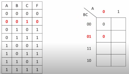
Gray Code means we only change on bit at a time. If you just remember this ordering she'll be right
Spotting The 1s
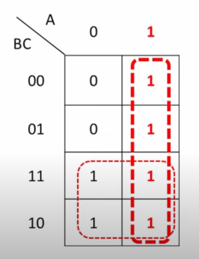
Once filled in we need to identify all of the squares with '1s'. We are not interested in zeros. We identify in rectangles only and there are other rules to follow. Here is our previous example filled in and 1s identified
Write Expression for each Rectangle
For each identified rectangle we write and expression for it.
- For Vertical rectangle 1 is always true when A=1 and regardless of the values of B or C
- For Horizontal rectangle 1 is always true when B=1 and regardless of the values of A or C
So the expression is A + B
The Rules
Although this does seem easy there are rules for rectangles
- No zeros in any rectangle
- All 1s in K-Map must be used by one rectangle
- The rectangle can only consist of power of 2 squares 1,2,4,8 - Not 3
- Rectangles can overlap but must have one unique cell
- Make rectangles as large as possible
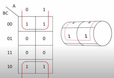
- Rectangles can cross from top to bottom
This last rule needs a picture. Luckily I have one
4 Inputs
Here is the exact same approach with 4 inputs. Now we see the x-axis also using gray number
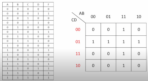
Here is the answers to this too.
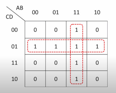
- The horizontal rectangle shows 1 when C is 1 and D is 0 - C.D̅
- The vertical rectangle shows 1 when A is 1 and B is 1 A.B
So the answer is C.D̅ + A.B
Full Truth Adder
Here is the truth table for the full adder
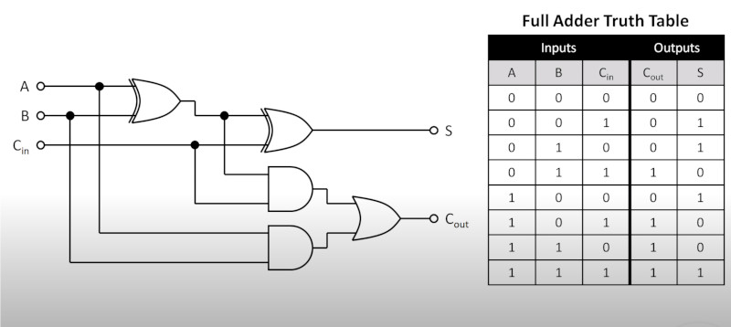
Here is how to do a Map for the full adder
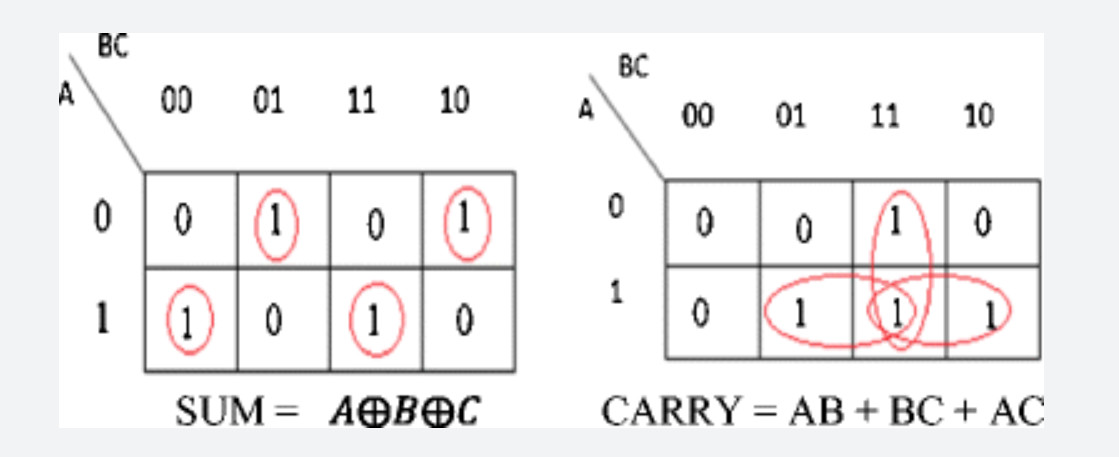
Usage of Boolean Algebra
Here are some examples in the real world of usage
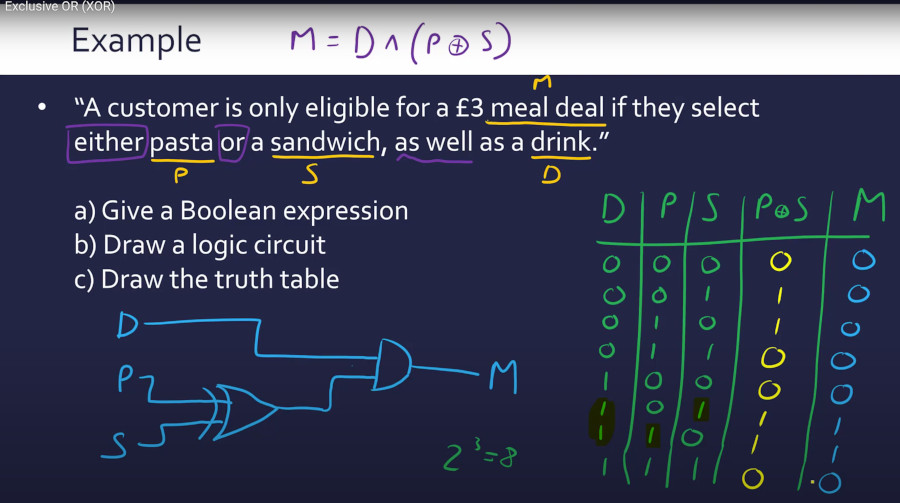
Boolean Algebra Worked XOR example
Really liked this explanation for XOR from youtube which combines all elements learning today. Truth tables are 2 to the power of inputs.
In Circuits
When we put logic on a circuit we can use boolean algebra to reduce the components required. Here is an example for Dave a eevblog (my hero today)
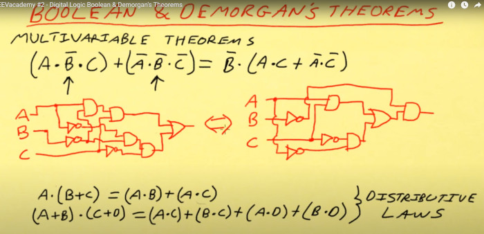
Using the above knowledge we have reduced the components from 5 input gates, 3 invertors, to 4 input gates, 3 invertors just using the distributive laws.
Below is Dave explaining an easy way to remember De Morgans's first theroem. Drop the bar and change the sign
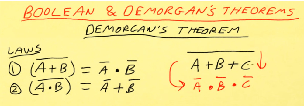
We can now start spotting patterns where we know we can reduce the gate count. Here we have two input NOR gates as inputs to a NOR gate. Using boolean algebra we can reduce this to an AND gate

